
Calibration method for steel rail profile measured by adopting laser displacement technology

A technology of laser displacement and technical measurement, which is applied in the direction of measuring devices, railway vehicle shape measuring devices, optical devices, etc., and can solve problems such as profile deformation

Inactive Publication Date: 2017-05-10
HUNAN UNIV +1
View PDF8 Cites 19 Cited by
  • Summary
  • Abstract
  • Description
  • Claims
  • Application Information

AI Technical Summary

Problems solved by technology

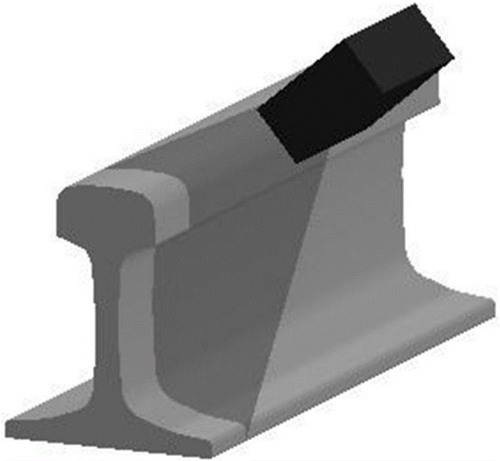
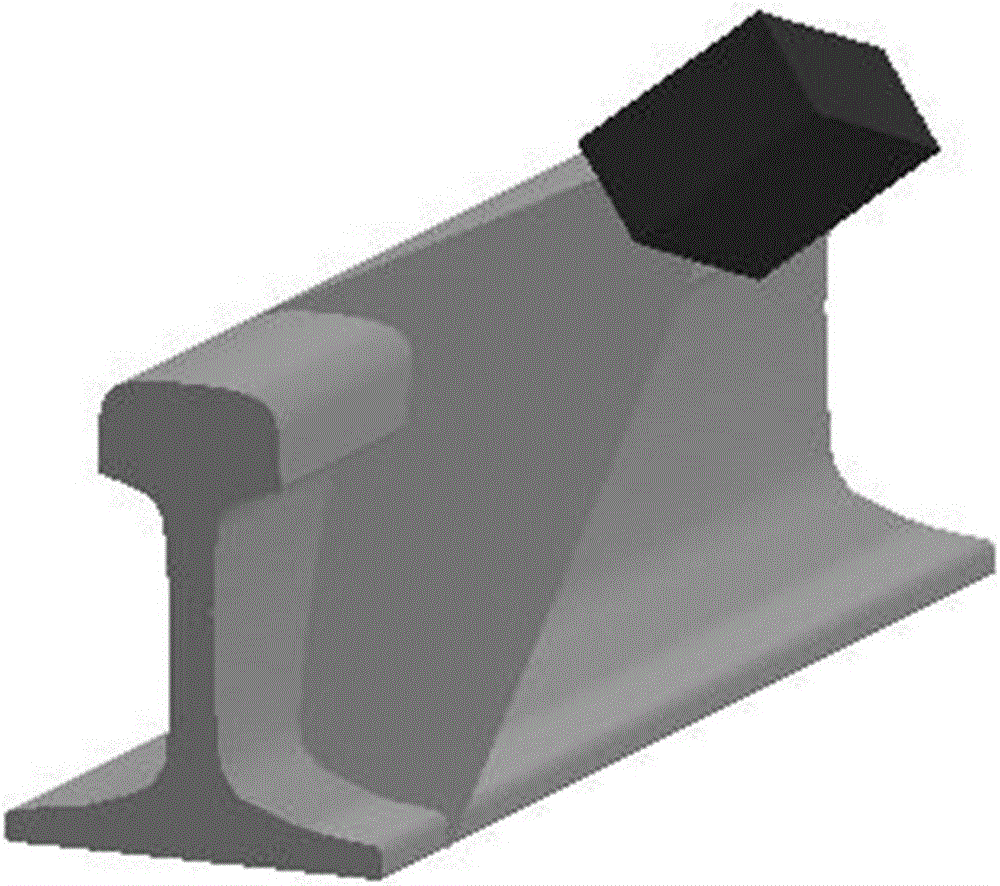
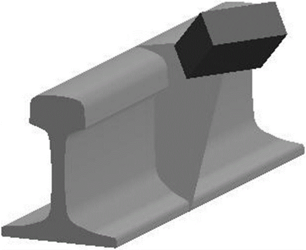
[0012] The purpose of the present invention is to provide a calibration method that can solve the profile deformation problem when using laser displacement technology to measure the profile of the rail, so as to realize the accurate calibration of the profile of the rail.

Method used


Image

  • Calibration method for steel rail profile measured by adopting laser displacement technology
  • Calibration method for steel rail profile measured by adopting laser displacement technology
  • Calibration method for steel rail profile measured by adopting laser displacement technology

Examples


Embodiment Construction

[0066] like Figure 7 Shown is the schematic flow chart of the method of the present invention: the calibration method for measuring the profile of the rail by the laser displacement technology provided by the present invention includes the following steps:

[0067] S1. Using the Ramer polygon segmentation algorithm, segment the rail profile into n+1 segments, and express the distance between adjacent segmentation points as (||P 2 -P 1 ||,||P 3 -P 2 ||,...,||P n -P n -1||), the vertical distance between adjacent split points is expressed as (y 2 -y 1 ,y 3 -y 2 ,...,y n -y n-1 ), and calculate the index value of the intersection of the rail jaw point and the rail bottom line; where n is a positive integer, the larger the value, the higher the calibration accuracy of the rail profile;

[0068] S2. For the rail waist section between the rail jaw point obtained in step S1 and the rail bottom straight line intersection, for each contour point k, define three closed areas...


PUM


Abstract

The invention discloses a calibration method for the steel rail profile measured by adopting a laser displacement technology. The calibration method comprises the steps of segmenting the steel rail profile, and calculating an index value; acquiring absolute affine invariants; acquiring a local affine non-deformation description feature vector set in an offline state and a local affine non-deformation description feature vector set in an operating state, matching feature vectors and acquiring a matching point set; calculating a transformation relational expression of profile data in the offline state and a transformation relational expression of profile data in the operating state; acquiring an affine transmission matrix; acquiring an affine transmission matrix set for each pair of matching points and completing data processing; and performing calibration on the steel rail profile according to the affine transmission matrix, the translation amount and the profile data transformation relational expressions. The invention innovatively proposes a new method for extracting, describing and matching the steel rail profile local affine invariants, puts forwards a quick iterative closest point algorithm to precisely adjust affine transformation parameters, and solves a problem of profile deformation in steel rail profile measurement performed by adopting the laser displacement technology, so that accurate correction is performed on the steel rail profile. In addition, the method is high in calculation speed and high in accuracy.

Description

technical field [0001] The invention specifically relates to a calibration method for measuring rail profile by laser displacement technology. Background technique [0002] The non-contact rail profile measurement system is widely used in the field of rail traffic inspection. The system uses a line-structured laser source and a CCD industrial camera to perceive the track, and directly measures various parameters such as the rail section as the track inspection vehicle travels, which can improve the efficiency of track maintenance operations. [0003] According to different CCD industrial camera data processing methods, the non-contact rail profile measurement technology can be divided into two types: laser vision technology and laser displacement technology. Laser imaging technology obtains the external parameters of the CCD camera imaging model by calibrating the vision sensor with high precision, and accurately converts the data in the two-dimensional image coordinate sys...

Claims


Application Information

Patent Timeline
Patent Type & Authority Applications(China)
IPC IPC(8): G01B11/24B61K9/08
CPCB61K9/08G01B11/24
Inventor 刘宏立王超马子骥金滩彭克立
Owner HUNAN UNIV
Learn More