
Experimental system for simulating fuel spray wetted walls

An experimental system and fuel technology, applied in the direction of internal combustion engine testing, etc., can solve the problems of affecting combustion and emission, splashing of lubricating oil film, increasing fuel consumption, etc., and achieve the effect of easy operation

Pending Publication Date: 2017-05-10
TIANJIN UNIV
View PDF4 Cites 17 Cited by
  • Summary
  • Abstract
  • Description
  • Claims
  • Application Information

AI Technical Summary

Problems solved by technology

[0003] On the one hand, the rebounded droplets after the fuel hits the wall can achieve secondary atomization, which is conducive to the formation of a homogeneous mixture; but on the other hand, the wet wall phenomenon will also cause dilution and splashing of the lubricating oil film on the surface of the cylinder liner, and the area near the wall Too rich mixture, increased fuel consumption and other issues, affecting combustion and emissions

Method used


Image

  • Experimental system for simulating fuel spray wetted walls
  • Experimental system for simulating fuel spray wetted walls
  • Experimental system for simulating fuel spray wetted walls

Examples


Embodiment 1

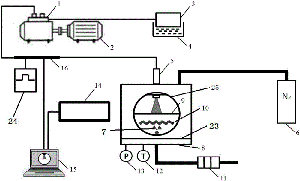
[0031] Such as figure 2 As shown, an experimental system for simulating the wetted wall of fuel spray includes a high-pressure fuel pump 1, a fuel tank 3, a fuel heating system 4, a fuel injector 5, a constant volume bomb 8, a constant volume bomb heating system, a vacuum pump 11, a temperature sensor 12, Pressure sensor 13, external test equipment 14, control system 15, high pressure fuel rail 16;

[0032] The high-pressure oil pump is connected to the driving motor 2, and the high-pressure oil pump is connected to the fuel tank, and the fuel tank is put into the fuel heating system;

[0033] The material of the constant volume bomb 8 is stainless steel, the top of the constant volume bomb is provided with the fuel injector, the constant volume bomb is connected with the high-pressure oil pump through the fuel injector, the bottom of the fuel injector is a spray hole, and the fuel injector is sprayed. The hole goes deep into the internal chamber of the constant volume bomb;...

Embodiment 2

[0045] An experimental system for simulating the wet wall of fuel spray, including high-pressure fuel pump, fuel tank, fuel heating system, fuel injector, constant volume bomb, constant volume bomb heating system, vacuum pump, temperature sensor, pressure sensor, external test equipment, control system, High pressure fuel rail;

[0046] The high-pressure oil pump is connected to the driving motor, and the high-pressure oil pump is connected to the fuel tank, and the fuel tank is put into the fuel heating system;

[0047] The material of the constant volume bomb is stainless steel, the top of the constant volume bomb is provided with the fuel injector, the constant volume bomb is connected with the high-pressure oil pump through the fuel injector, and the bottom of the fuel injector is a spray hole. Go deep into the inner chamber of the constant volume bomb; four vertical outer walls of the constant volume bomb are provided with windows, and a side end cover is arranged between...


PUM

PropertyMeasurementUnit
Diameteraaaaaaaaaa
Diameteraaaaaaaaaa
Diameteraaaaaaaaaa

Abstract

The invention discloses an experimental system for simulating fuel spray wetted walls. The experimental system comprises a high-pressure oil pump, an oil tank, a fuel heating system, an oil sprayer, a constant-volume bomb, a constant-volume bomb heating system, a vacuum pump, a temperature sensor, a pressure sensor, external test equipment, a control system and a high-pressure oil rail. The experimental system has the advantages that oil spray wall hitting procedures in actual cylinders can be accurately simulated, a plurality of variable conditions can be controlled by the control system, comprehensive and detailed research on the fuel wall hitting procedures can be carried out, the experimental system can be matched with optical measurement equipment, accordingly, change rules of micro-variables in fuel wall wetting procedures can be intuitively reflected, and intensive research on fuel wall wetting mechanisms of engines can be carried out by the experimental system; experimental devices are easy and convenient to operate, and measurement results are important reference for improving the early spray performance of the engines.

Description

technical field [0001] The invention belongs to the technical field of engines and is mainly used for simulating the process of engine spray wet walls, in particular to an experimental system for simulating fuel spray wet walls. Background technique [0002] In order to achieve the goal of efficient and clean engine combustion, a number of new internal combustion engine combustion technologies centered on "low temperature combustion" have received widespread attention, such as homogeneous compression ignition (HCCI) and premixed compression ignition (PCCI). The early injection technology is a key technology to realize the low-temperature combustion mode of the engine. The early injection technology generally refers to injecting fuel into the cylinder at the earlier fuel injection timing (-90°~-120°CA ATDC) of the engine to Prolong the mixing time of oil and gas, reduce the combustion temperature in the cylinder, so that the combustion is more complete and the harmful emissio...

Claims


Application Information

Patent Timeline
IPC IPC(8): G01M15/04
CPCG01M15/04
Inventor 梁兴雨于晗正男舒歌群王月森张洪升
Owner TIANJIN UNIV
Features
  • Generate Ideas
  • Intellectual Property
  • Life Sciences
  • Materials
  • Tech Scout
  • Unparalleled Data Quality
  • Higher Quality Content
  • 60% Fewer Hallucinations
Learn More