Flow cytometer light beam shaping system based on gradient refractive index lens

A graded refractive index and flow cytometry technology, which is applied in the field of flow cytometer instruments, can solve the problems of difficult adjustment, small beam expansion ratio, and inability to change the shape of the spot, and achieves the effect of simple use and convenient installation.

Active Publication Date: 2017-05-10
BEIJING INFORMATION SCI & TECH UNIV
View PDF6 Cites 5 Cited by
  • Summary
  • Abstract
  • Description
  • Claims
  • Application Information

AI Technical Summary

Problems solved by technology

In October 2010, Shang Jianli and others from the School of Optoelectronic Science and Engineering of Huazhong University of Science and Technology proposed a new type of refractive Gaussian beam flattener, which achieved a good shaping effect with only one aspheric lens, improving the traditional shaping effect. The device has the disadvantages of large volume and difficult adjustment, but this system is only suitable for Gaussian beam shaping schemes with small beam expansion multiples
In June 2011, Ma Haotong and others from the School of Optoelectronic Science and Engineering of the National University of Defense Technology proposed an improved method for Gaussian beam shaping by Galilean aspheric lens groups, so that the shaping system can not only expand and shape the laser beam, but also shape the laser beam. At the same time, the shaping effect is close to the diffraction limit, but the surface curve of the designed aspheric surface is not monotonous, which makes the processing very difficult
[0005] To sum up, at present, domestic and foreign researchers use aspheric lens groups to shape Gaussian beams, which are mainly based on the theoretical basis of axisymmetric optical systems. modulation without changing the shape of the spot

Method used


Image

  • Flow cytometer light beam shaping system based on gradient refractive index lens
  • Flow cytometer light beam shaping system based on gradient refractive index lens
  • Flow cytometer light beam shaping system based on gradient refractive index lens

Examples


Embodiment 1

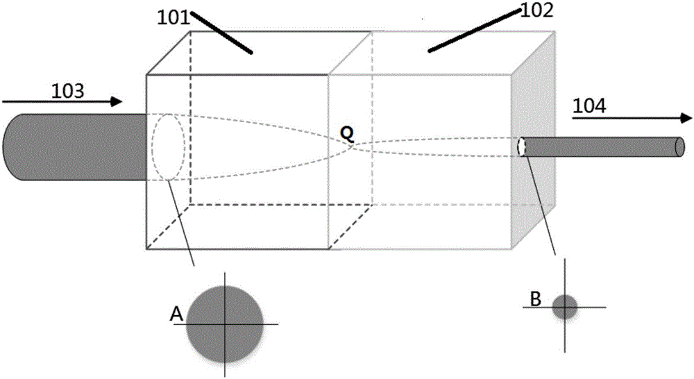
[0023] figure 1 It is a system diagram of a flow cytometer beam shaping system based on a gradient index lens of the present invention. like figure 1 As shown, a graded index lens-based flow cytometry beam shaping system includes a first lens 101, a second lens 102 and a laser (not shown). The incident laser beam 103 emitted by the laser passes through the first lens 101 and the second lens 102 to form an outgoing laser beam 104 . The cross-sectional spot of the incident laser beam 103 is A, and the cross-sectional spot of the outgoing laser beam is B. The difference between the cross-section spot is B and the cross-section spot is A is that the size of the spot has changed.

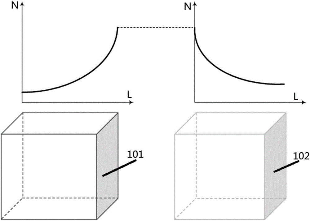
[0024] The incident laser beam 103 reaches the first lens 101, since the refractive index of the first lens 101 gradually increases along the axial direction, as figure 2 As shown in the figure on the left, the vertical axis N represents the refractive index, and the horizontal axis L represents the...

Embodiment 2

[0030] image 3 It is a graph showing the variation of the refractive index of the gradient index lens in Example 2 of the present invention. like image 3 As shown, the left figure represents the refractive index change curve of the first lens 101, and the right figure represents the refractive index change curve of the second lens 102. The difference between this embodiment and Embodiment 1 is that the refractive index of the gradient index lens occurs The absolute value of each slope of the lens refractive index curve in this embodiment increases gradually as the length L increases.

[0031] The incident laser beam reaches the first lens, such as image 3As shown, the vertical axis N represents the refractive index, and the horizontal axis L represents the length of the lens. The refractive index N of the first lens increases with the increase of the length L, and the trend of the refractive index curve is an increasing curve of a parabolic function. Compared with the si...

Embodiment 3

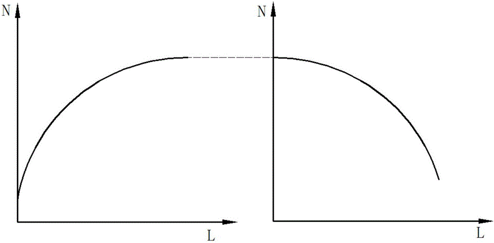
[0033] Figure 4 It is a graph showing the variation of the refractive index of the graded-index lens in Example 3 of the present invention. like Figure 4 As shown, the left figure represents the refractive index change curve of the first lens 101, and the right figure represents the refractive index change curve of the second lens 102. The difference between this embodiment and Embodiment 1 is that the refractive index of the gradient index lens occurs In this embodiment, the trend of the lens refractive index curve is a linear function graph, the slope of the refractive index curve is equal everywhere, and the spot size changes at a uniform speed when the laser beam propagates in the gradient index lens.


PUM


Abstract

The invention discloses a flow cytometer light beam shaping system based on a gradient refractive index lens. The light beam shaping system comprises a lens set and a laser. The flow cytometer light beam shaping system is characterized in that a light beam which is transmitted from the laser is convergent through an optical lens set with a direction-related refractive index characteristic so that different axial magnifying powers exist in different directions, thereby realizing ovalization of a convergent light spot. The flow cytometer light beam shaping system realizes single-lens shaping of a flow cytometer spot-lighting light spot and greatly reduces system complexity and mounting-and-adjusting difficulty of a double-cylindrical-surface lens.

Description

technical field [0001] The invention relates to the instrument field of a flow cytometer, in particular to a flow cytometer beam shaping system based on a gradient refractive index lens. Background technique [0002] In many practical applications of lasers, such as laser-driven nuclear fusion, laser material processing, laser medical treatment and other fields, laser beams with uniform spatial distribution of light intensity are often required. However, the laser beam emitted by the actual laser is usually a Gaussian beam, so a specially designed optical system is required to shape the Gaussian beam into a flat-top beam with uniform light intensity distribution. [0003] After the further development of optical modulation technology, there are many spatial shaping methods for beams today. In addition to the diaphragm interception method used initially, aspheric lens groups, holographic filters, binary phase, amplitude modulation gratings, and phase beams can also be used. ...

Claims


Application Information

Patent Timeline
Patent Type & Authority Applications(China)
IPC IPC(8): G02B27/09
CPCG02B27/0955
Inventor 祝连庆刘超娄小平潘志康董明利孟晓辰张文昌
Owner BEIJING INFORMATION SCI & TECH UNIV
Why Eureka
Try Eureka