Jump button riveting and flanging integrated tooling and processing method thereof

A one-piece, jump-button technology, applied in the direction of emergency protection devices, emergency protection device manufacturing, electrical components, etc., can solve problems affecting product quality, low processing efficiency, product deformation, etc., to ensure the quality of riveting and flanging, installation Fast, easy-to-place effects

Active Publication Date: 2018-10-30
JIANGSU DAQO KFINE ELECTRIC
View PDF2 Cites 2 Cited by
  • Summary
  • Abstract
  • Description
  • Claims
  • Application Information

AI Technical Summary

Problems solved by technology

[0008] The purpose of the present invention is to overcome the problems of the existing riveting processing for jumper parts, such as low processing efficiency, easy deformation of the product or insufficient riveting, and affecting product quality, and provides a jumper clamp, jumper riveting and flanging integrated Type tooling and its processing method; using the technical scheme provided by the invention, the operation is simple, the jump button can be assembled at one time, the quality of riveting and flanging is reliable, and the tooling has small size, smart structure, beautiful appearance, easy operation, and low cost. features

Method used


Image

  • Jump button riveting and flanging integrated tooling and processing method thereof
  • Jump button riveting and flanging integrated tooling and processing method thereof
  • Jump button riveting and flanging integrated tooling and processing method thereof

Examples


Embodiment 1

[0046] to combine Figure 5 , a jumper fixture in this embodiment, including a drawer seat 81 and a pull rod 82, the draw rod 82 is connected to one end of the drawer seat 81, and the drawer rod 82 is used to push the drawer seat 81 into and out of the tooling . Along the length direction of the drawer seat 81, at least one jumper placement station is arranged, and the jumper placement station is used for initial assembly of each part of the jumper before the parts of the jumper are not riveted. This embodiment is designed to set a plurality of snap button placement stations along the length direction of the drawer seat 81. Compared with the traditional staff, the jump button workpiece is manually clamped in 4 times, and the riveting and flanging process of the jump button is completed in 4 times. That is to say, the assembly of multiple snap buttons can be completed, and the processing efficiency is doubled, which also reduces the labor intensity of the staff and liberates p...

Embodiment 2

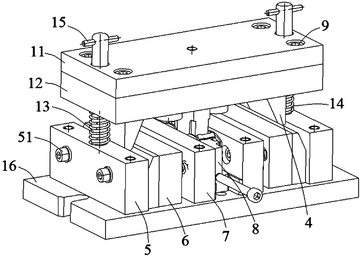
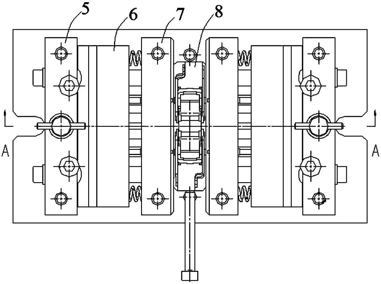
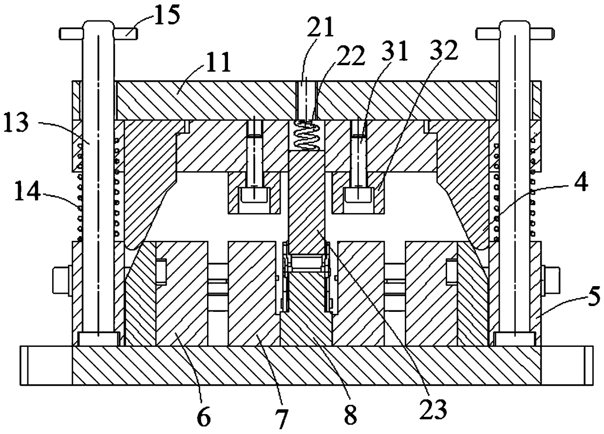
[0050] to combine figure 1 , figure 2 and image 3 , a jump button riveting and flanging integrated tooling of this embodiment, including an upper die, a guide post 13, a guide post spring 14, a bottom plate 16, a first lower die column plate 5, a slider assembly 6, and a second lower die Column plate 7 and jumper clip 8 described in Embodiment 1. Wherein, the upper mold includes an upper baffle plate 11 and an upper mold fixed plate 12, and the upper baffle plate 11 and the upper mold fixed plate 12 are connected by fixing pins 9, and the guide post 13 is connected in series with the upper mold and the first lower mold column plate 5 And the bottom plate 16, the end of the guide post 13 passing through the upper baffle plate 11 is horizontally inserted into the limit pin 15, and the limit pin 15 is used to limit the upward position of the upper mold. The guide post spring 14 is passed through the guide post 13, and the guide post spring 14 is used to help the upper die r...

Embodiment 3

[0063] The snap-off fixture of this embodiment is basically the same as that of Embodiment 1; the integrated tooling of the snap-off riveting and flanging is basically the same as that of Embodiment 2, the difference being that the snap-off fixture of this embodiment is set along the length direction of the drawer seat 81 There are four jumper placement stations, and 4 jumper placement stations are set in pairs. Correspondingly, the punch layout of the slider assembly 6 and the column plate 7 of the second lower die in the one-piece tooling for jumper riveting and flanging are also adaptively changed.

[0064]The jumper clamp, jumper riveting and flanging integrated tooling described in Examples 1-3 adopts an integrated modular design and can be installed on different presses or desktop punching machines, which is convenient for production scheduling and easy to operate, making the jumper One-time assembly is completed, the quality of riveting and flanging is reliable, and the...


PUM


Abstract

The invention discloses a jump catch clamp, an integrated tool for jump catch riveting and flanging and a machining method thereof, and the jump catch clamp is a special clamp. The tool disclosed by the invention comprises an upper die, a guide post, a guide post spring, a base plate, sliding block assemblies, a first lower die upright post plate and the jump catch clamp, wherein the guide post is serially connected to the upper die, the first lower die upright post plate and the base plate; the guide post spring is arranged on the guide post in a penetrating manner; the jump catch clamp can be inserted in a drawer groove in the middle part of the base plate; the sliding block assemblies capable of moving horizontally are arranged on the left side and the right side of the jump catch clamp; a riveting punch is arranged on the side, close to the jump catch clamp, of each sliding clock assembly, and an inclined wedge surface is arranged on the other side of each sliding block assembly; an inclined pressing block is arranged above each inclined wedge surface; the inclined pressing blocks are connected with the upper die; and the inclined pressing blocks are provided with inclined wedge surfaces matched with the inclined wedge surfaces of the sliding block assemblies. The jump catch can be assembled at a time, the riveting and flanging quality is reliable, and the production efficiency is improved.

Description

technical field [0001] The invention relates to a special fixture, more specifically, relates to a snap button riveting and flanging integrated tooling and a processing method thereof. Background technique [0002] Riveting is one of the most common processing techniques in the industrial production process of products, which is to rivet two or more workpieces together. With the continuous deepening of my country's power grid transformation, the demand for molded case circuit breaker products continues to increase. In order to ensure the safety, reliability and continuity of power supply and distribution, the requirements for circuit breakers are getting higher and higher. Many components in low-voltage circuit breaker products are riveted by two or more parts. [0003] The jumper is one of the core components of the circuit breaker, and its processing quality is related to the product quality and production efficiency of the entire circuit breaker. Such as Figure 4 As sh...

Claims


Application Information

Patent Timeline
Patent Type & Authority Patents(China)
IPC IPC(8): H01H69/00B21J15/38B21J15/42B21D19/00
CPCB21D19/00B21J15/38B21J15/42H01H69/00
Inventor 李飞黄良荣
Owner JIANGSU DAQO KFINE ELECTRIC
Why Eureka
Try Eureka