Slow wave structure for high-power output of traveling wave tubes

A slow-wave structure and high-power technology, which is applied in the field of slow-wave structures, can solve problems such as hindering the development of helical traveling wave tubes, difficult processing, and complex structures, and achieve the goals of improving high-power output, easy processing, and expanding application range. Effect

Inactive Publication Date: 2017-05-10
UNIV OF ELECTRONICS SCI & TECH OF CHINA
View PDF3 Cites 3 Cited by
  • Summary
  • Abstract
  • Description
  • Claims
  • Application Information

AI Technical Summary

Problems solved by technology

Due to the small size and complex structure of the slow wave structure of the helical traveling wave tube, it is di...

Method used


Image

  • Slow wave structure for high-power output of traveling wave tubes
  • Slow wave structure for high-power output of traveling wave tubes
  • Slow wave structure for high-power output of traveling wave tubes

Examples


Embodiment Construction

[0018] This embodiment is a design and application of a slow wave structure for high power output of a traveling wave tube in the Ka band.

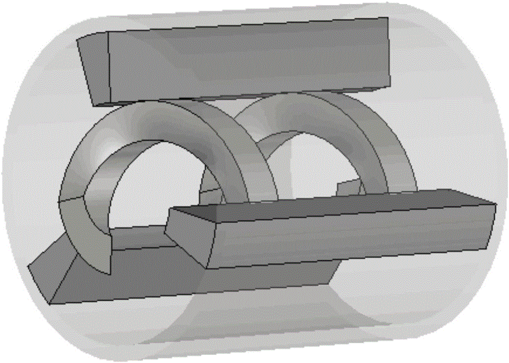
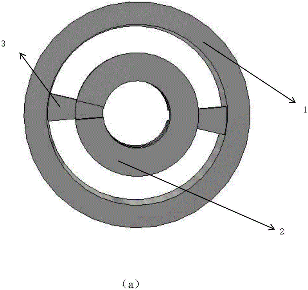
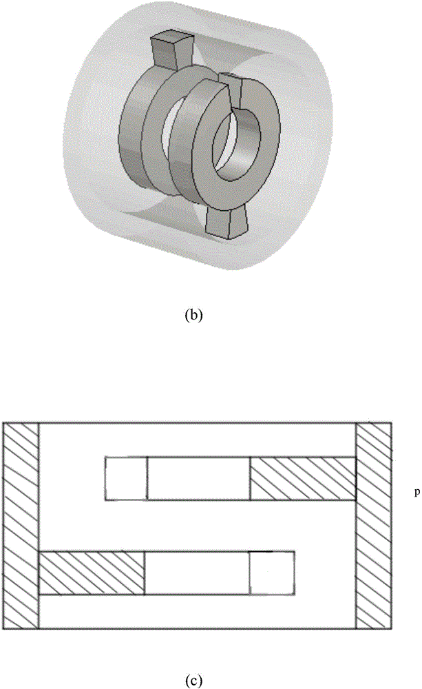
[0019] The slow wave structure described in this embodiment includes a cylindrical metal shell, a number of concentric open metal rings arranged in the shell, and a support structure for fixing the metal rings. The support structures of two adjacent metal rings are arranged symmetrically. on both sides.

[0020] The material of the supporting structure is metallic copper, its cross section is fan-shaped, the thickness is 0.25mm, and the angle is 18°. The inner diameter of the metal case is 0.80mm and the thickness is 0.20mm. The material of the concentric metal ring is metal copper, the inner diameter is 0.30mm, the thickness is 0.25mm, the distance between the two concentric metal rings is 0.30mm, the distance between the metal ring and the inner wall of the shell is 0.15mm, the metal ring The cross section of the ring opening is fan-s...


PUM


Abstract

The invention discloses a slow wave structure for high-power output of traveling wave tubes, and belongs to the field of microwave electric vacuum. The slow wave structure comprises a cylindrical metal shell, a plurality of concentric open metal rings arranged in the shell, and a metal support structure for fixing the metal rings. The support structure of the slow wave structure is made of a metal material, and can achieve a function of heat dissipation to a certain extent. Within the working frequency range, the slow wave structure has a much larger coupling impedance curve than a helix slow wave structure, and can achieve well and effective interaction and exchange of energy. The problem that the coupling impedance of a general slow wave structure is too small is solved to a certain extent. The slow wave structure of the invention is easy to machine. The problem concerning high power output of traveling wave tubes with larger bandwidth is well improved. The application scope of travelling wave tubes is expanded.

Description

technical field [0001] The invention belongs to the field of microwave electric vacuum, and in particular relates to a slow wave structure used for high power output of a traveling wave tube. Background technique [0002] Traveling wave tube is a very important vacuum electron tube in the field of microwave technology. Because traveling wave tubes have excellent characteristics such as high power, wide frequency band, large dynamic range, low noise, and high gain, they are widely used in various electronic equipment such as radar, communication, television, broadcasting, telemetry, and electronic countermeasures. [0003] At present, in order to meet the requirements of different applications, traveling wave tubes have developed into a large family, which is divided into slow wave structures. There are two types of traveling wave tubes that have been developed: helical traveling wave tubes - this type of tube traveling wave tubes The bandwidth is the widest. Due to the limi...

Claims


Application Information

Patent Timeline
IPC IPC(8): H01J23/42H01J23/00
CPCH01J23/005H01J23/42
Inventor 刘鹏飞高茂原路志刚宫玉彬
Owner UNIV OF ELECTRONICS SCI & TECH OF CHINA
Why Eureka
Try Eureka