Plasma jet flow generation device

A generation device and plasma technology, applied in the direction of plasma, discharge tube, electrical components, etc., can solve the problems of shortening the length of plasma jet plume, reducing the energy of plasma jet, and short length of plasma plume, etc. Uniform and stable in vitro, easy to discharge, and large spraying distance

Active Publication Date: 2017-05-10
DALIAN NATIONALITIES UNIVERSITY
View PDF7 Cites 6 Cited by
  • Summary
  • Abstract
  • Description
  • Claims
  • Application Information

AI Technical Summary

Problems solved by technology

The existing plasma jet generating device has a large voltage during the discharge process, and the length of the formed plasma plume is short, and the energy loss in the tube of the plasma jet device is relatively large, thereby reducing the energy of the plasma jet and making the length of the plasma jet plume variable. short and low energy

Method used


Image

  • Plasma jet flow generation device

Examples


Embodiment Construction

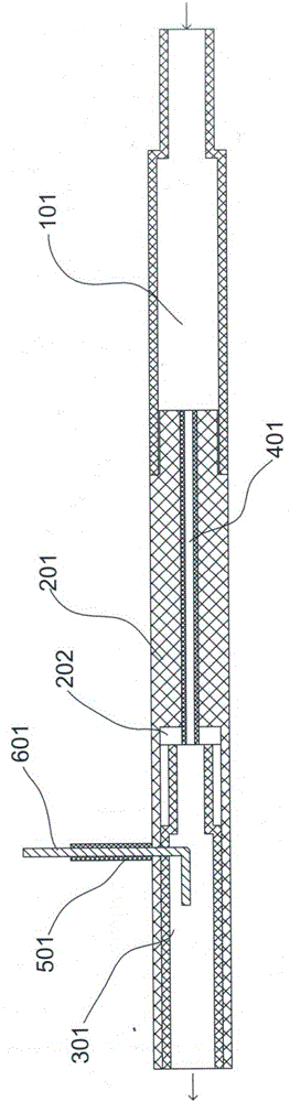
[0018] Next, the present invention will be described in detail in conjunction with the accompanying drawings

[0019] like figure 1 In the shown plasma jet generating device, the air pipe 101 is a reducing pipe made of insulating material, one end of which is an air inlet end, and the other end is an air outlet end, the inner diameter of the air inlet end is smaller than the inner diameter of the air outlet end, and the inner diameter of the air pipe is The outlet end is screwed to the discharge seat 201 made of insulating material, and a cavity 202 is opened inwardly from the non-connecting end of the discharge seat. There is a discharge tube 301 made of insulating material in the cavity, and the discharge tube is a reducing tube. , one end of the discharge tube is the air intake end, and the other end is the injection end, the inner diameter of the air intake end is smaller than the inner diameter of the injection end; the air intake end of the discharge tube communicates wi...


PUM


Abstract

The invention relates to a plasma jet flow generation device. An air outlet end of an air pipe is in threaded connection with a discharge seat made of insulation material, a hollow cavity is inwards formed in a non-connection end of the discharge seat, a discharge pipe made of insulation material is arranged in the hollow cavity, an air inlet end is arranged at one end of the discharge pipe, a spraying end is arranged at the other end of the discharge pipe, the air inlet end of the discharge pipe communicates with the interior of the air pipe through an intermediate pipe made of insulation material, a branch pipe is arranged on the discharge seat and communicates with the hollow cavity in the discharge seat, the branch pipe is made of insulation material, a high-voltage electrode is arranged in the branch pipe, one end of the high-voltage electrode extends out of the branch pipe, and the other end of the high-voltage electrode extends into the discharge pipe. Compared with the prior art, the plasma jet flow generation device has the advantages of long spaying distance, large plasma density, high continuous discharge performance and the like.

Description

technical field [0001] The invention belongs to the field of plasma generation, in particular to a plasma jet generation device. Background technique [0002] Plasma is the fourth state of matter different from solid, liquid and gas. Low-temperature plasma can effectively kill bacteria and microorganisms existing in the air and on the surface of objects. The existing plasma jet generating device has a large voltage during the discharge process, and the length of the formed plasma plume is short, and the energy loss in the tube of the plasma jet device is relatively large, thereby reducing the energy of the plasma jet and making the length of the plasma jet plume variable. Short and low energy. Contents of the invention [0003] The object of the present invention is to provide a plasma jet generating device with long spraying distance, high plasma density, strong continuous discharge and uniform and stable plasma generation. [0004] Concrete technical scheme of the pres...

Claims


Application Information

Patent Timeline
Patent Type & Authority Applications(China)
IPC IPC(8): H01J37/32H05H1/34
CPCH01J37/32431H05H1/3405
Inventor 刘东平田恩强
Owner DALIAN NATIONALITIES UNIVERSITY
Why Eureka
Try Eureka