Sucker and adsorption method thereof

A suction cup and main body technology, which is applied in the field of semiconductor device manufacturing, can solve problems such as inability to generate adsorption force, inability to effectively absorb warped substrates, and 04 adsorption design not involved in warped substrates, achieving effective adsorption, high adaptability to working conditions, The effect of reducing wear

Active Publication Date: 2017-05-10
SHANGHAI MICRO ELECTRONICS EQUIP (GRP) CO LTD +1
View PDF4 Cites 4 Cited by
  • Summary
  • Abstract
  • Description
  • Claims
  • Application Information

AI Technical Summary

Problems solved by technology

[0003] The suction cup provided by the prior art includes a suction cup main body 01, a through hole 015 for connecting the substrate 02, and a vacuum hole 014 communicating with an external vacuum source. The vacuum hole 014 forms a vacuum chamber 011 with the sealing ring 012 and the substrate 02, and the external atmospheric pressure The pressure difference between the vacuum chamber 011 and the vacuum chamber 011 produces an adsorption force that firmly and reliably presses the substrate 02 on the suction cup body 01. At the same time, there are several bumps 013 features evenly distributed in the vacuum chamber 011, which play a supporting role for the substrate 02. , to prevent the substrate 02 from being deformed due to the adsorption force, which affects the lithography accuracy
[0004] For substrates with better surface shapes, the suction cups in the prior art can effectively absorb them, but they cannot effectively adsorb them for warped substrates. The reasons are as follows: image 3 As shown, the suction cup body 01, the sealing ring 012 and the warped substrate 04 form a vacuum chamber 011 together. It is expected that the warped substrate 04 will be adsorbed on the suction cup 01 by the adsorption force generated by the pressure difference between the vacuum chamber 011 and the external atmosphere.
However, since the main warped shape of the warped substrate 04 is the "bowl shape" shown in the figure, there is a relatively large gap between the substrate 04 and the right side of the vacuum chamber 011 formed by the suction cup 01 (the size of the gap is affected by the warping degree of the substrate), thus causing The vacuum chamber 011 communicates with the external atmosphere and cannot form an effective pressure difference with the external atmosphere, so it cannot generate effective adsorption force to adsorb the substrate 04 on the suction cup 01
Adsorption design for warped substrate 04 is not involved in existing patents and literature

Method used


Image

  • Sucker and adsorption method thereof
  • Sucker and adsorption method thereof
  • Sucker and adsorption method thereof

Examples


Embodiment Construction

[0034] The specific embodiment of the invention will be described in further detail below in conjunction with the accompanying drawings.

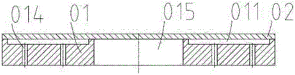
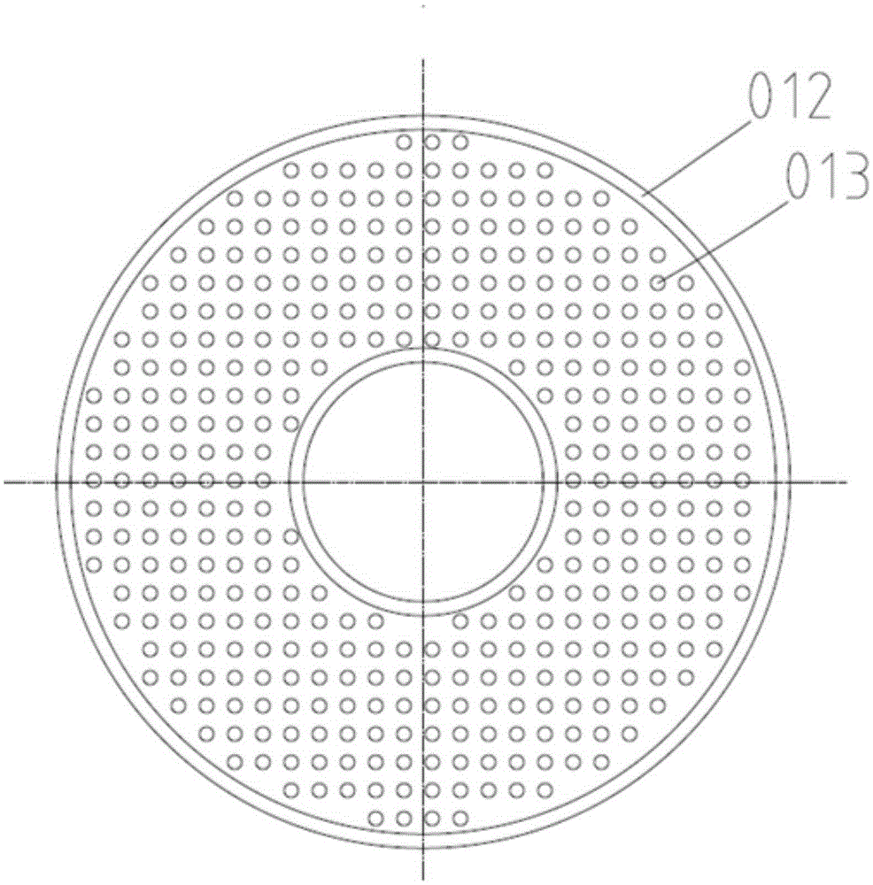
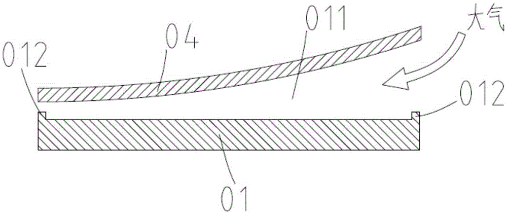
[0035] Such as Figure 4 with Figure 5 As shown, the present invention provides a suction cup, including a suction cup body 03, wherein, the center of the suction cup body 03 is provided with a through hole 035 for substrate transfer, and the suction cup body 03 is provided with at least one protrusion protruding from the suction cup body 03. And the sealing ring 032 concentrically distributed with the through hole 035, the sealing ring 032 is provided with an annular groove 031, and the annular groove 031 is provided with a number of vacuum holes 034 communicated with the external vacuum source, correspondingly the vacuum The hole 034 passes through the suction cup body 03 corresponding to the annular groove 031 and communicates with the vacuum source. When the substrate 04 is adsorbed, a vacuum is introduced from the vacuum hole 034, a...


PUM

PropertyMeasurementUnit
diameteraaaaaaaaaa
widthaaaaaaaaaa

Abstract

The invention discloses a sucker and an adsorption method thereof. The sucker comprises a sucker body of which the center is provided with a through hole for connecting a substrate. The sucker body is equipped with at least one sealing ring which protrudes from the sucker body and is distributed concentric with the through hole. The sealing ring has a ring groove. The ring groove is internally provided with a plurality of vacuum holes communicated with an external vacuum source. When the sucker absorbs the substrate, vacuum is pumped in from the vacuum holes, and the ring groove between the sealing ring and the substrate forms a vacuum cavity. By adoption of a ring vacuum cavity structure, the gap between the substrate and the ring vacuum cavity can be improved gradually. After the ring vacuum cavity at an inner ring is absorbed, the gap between the ring vacuum cavity at an adjacent outer ring and the substrate will be reduced. Finally, the warped substrate is absorbed effectively.

Description

technical field [0001] The invention relates to a suction cup and an adsorption method thereof, which are used for absorbing substrates, especially warped substrates, in the process of photolithography, and belong to the field of semiconductor device manufacturing. Background technique [0002] Photolithography is a process technology for exposing mask patterns to images on substrates, and is an important step in the semiconductor device manufacturing process. Known lithographic apparatuses include step-and-repeat and step-and-scan. In the above-mentioned lithography equipment, corresponding devices are required as the carrier of the reticle and the substrate, and the carrier loaded with the reticle / substrate generates precise mutual motion to meet the requirements of lithography. During the mutual movement of the reticle and substrate, it must be ensured that the reticle and substrate are always reliably positioned. Devices that are used directly to position the substrate...

Claims


Application Information

Patent Timeline
Patent Type & Authority Applications(China)
IPC IPC(8): H01L21/683
CPCH01L21/6838
Inventor 郑清泉方洁夏海
Owner SHANGHAI MICRO ELECTRONICS EQUIP (GRP) CO LTD
Why Eureka
Try Eureka