Battery automatic electrolyte injection equipment
A liquid injection and battery technology, applied in the field of battery automatic liquid injection equipment, can solve the problems of low production efficiency, multi-power components, etc., and achieve the effects of high production efficiency, improved absorption effect, and low use cost
- Summary
- Abstract
- Description
- Claims
- Application Information
AI Technical Summary
Problems solved by technology
Method used
Image

Examples
Embodiment Construction
[0027] In order to make the object, technical solution and advantages of the present invention clearer, the present invention will be further described in detail below in conjunction with the accompanying drawings and embodiments. It should be understood that the specific embodiments described here are only used to explain the present invention, not to limit the present invention.
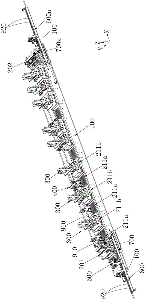
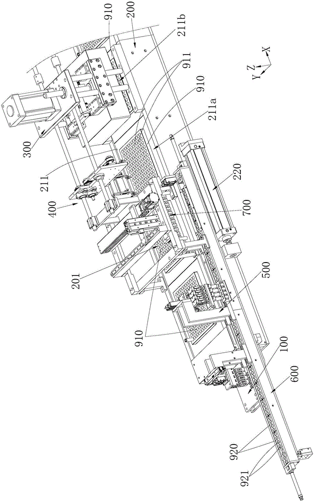
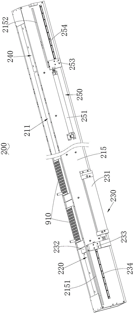
[0028] see Figure 1 to Figure 3 , the automatic battery liquid injection device provided by the embodiment of the present invention includes a first battery holder 910 having several first positioning slots 911; a delivery device 200 for delivering the first battery holder 910, which includes a first The delivery slot 211 and the first pushing mechanism 220 for pushing the first battery holder 910 from the front end of the first delivery slot 211 to the end of the first delivery slot 211, the first delivery slot 211 is formed between the front end and the end At least two liquid injection levels ...
PUM
 Abstract
Description
Claims
Application Information
 - Generate Ideas
- Intellectual Property
- Life Sciences
- Materials
- Tech Scout
- Unparalleled Data Quality
- Higher Quality Content
- 60% Fewer Hallucinations
Browse by: Latest US Patents, China's latest patents, Technical Efficacy Thesaurus, Application Domain, Technology Topic, Popular Technical Reports.
© 2025 PatSnap. All rights reserved.Legal|Privacy policy|Modern Slavery Act Transparency Statement|Sitemap|About US| Contact US: help@patsnap.com