Battery wireless charging pile with timing function

A battery wireless and timing function technology, applied in battery circuit devices, electric vehicle charging technology, charging stations, etc., can solve the problems of inconvenient charging of electric vehicles and the impact of traffic order, so as to improve the utilization rate, relieve work pressure, increase The effect of light intensity

Inactive Publication Date: 2017-05-10
ANHUI ZHIRUI ELECTRIC
View PDF5 Cites 1 Cited by
  • Summary
  • Abstract
  • Description
  • Claims
  • Application Information

AI Technical Summary

Problems solved by technology

China's electric vehicles have entered the stage of industrialization from the stage of research and development, and the rising electric vehicle industry in China is showing vigorous vitality. When driving a car, sometimes 12 or 24 batteries are used, and sometimes more , so the public ultra-fast wireless charging station will be the infrastructure for the commercialization of pure electric vehicles. Ultra-fast wireless charging stations are still not popular. Most of the existing wireless charging piles are installed in charging stations. Electric vehicles must be driven from all over the city to nearby charging stations for charging, which brings great pressure to the staff of charging stations. The large number of electric vehicles has a serious impact on the traffic order of the roads near the charging station, and some electric vehicle owners live in high-rise buildings, and it is inconvenient to charge electric vehicles at home, so it is necessary to solve the problem of electric vehicle charging

Method used


Image

  • Battery wireless charging pile with timing function
  • Battery wireless charging pile with timing function
  • Battery wireless charging pile with timing function

Examples


Embodiment Construction

[0017] The following will clearly and completely describe the technical solutions in the embodiments of the present invention with reference to the accompanying drawings in the embodiments of the present invention. Obviously, the described embodiments are only some, not all, embodiments of the present invention.

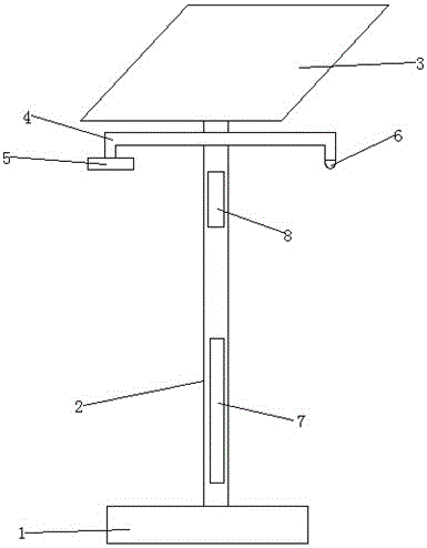
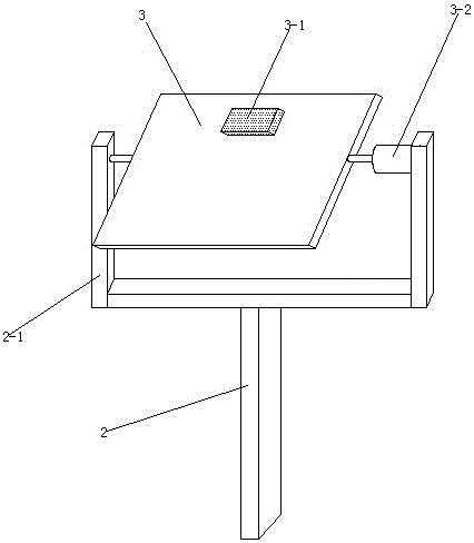
[0018] refer to Figure 1-3 , a battery wireless charging pile with timing function, including a base 1, a column 2 is arranged on the base 1, the column 2 is a hollow structure, a battery 7 is arranged inside the column 2, and a fixed frame 2-1 is fixed on the top of the column 2, and fixed The frame 2-1 is a concave structure, a motor 3-2 is fixedly installed on one side inner wall of the fixed frame 2-1, and a rotating shaft is connected to the other side inner wall of the fixed frame 2-1, and the motor 3-2 A photovoltaic power generation panel 3 is connected to the output shaft, and the end of the photovoltaic power generation board 3 away from the motor 3-2 is r...


PUM


Abstract

The invention discloses a battery wireless charging pile with a timing function. The battery wireless charging pile comprises a base, the base is provided with an upright column, the upright column is of a hollow structure, the upright column is internally provided with a storage battery, a fixation frame is fixed at the top portion of the upright column, the fixation frame is of a concave-shaped structure, the inner wall of one side of the fixation frame is fixedly provided with a motor, the inner wall of the other side of the fixation frame is connected with a rotating shaft, the output shaft of the motor is connected with a photovoltaic generating panel, and one end, which is away from the motor, of the photovoltaic generating panel is rotationally connected with the rotating shaft. According to the invention, the illumination intensity received by the photovoltaic generating panel can be increased, the utilization rate of solar energy by the photovoltaic generating panel is improved, more power resources are stored, electric automobiles can be charged by effective use of power resources stored by photovoltaic street lamps, charging points of the electric automobiles are dispersed and transferred, work pressure of a charging station is effectively alleviated, and traffic environment nearby the charging station can be guided and regulated.

Description

technical field [0001] The invention relates to the technical field of wireless charging piles, in particular to a battery wireless charging pile with a timing function. Background technique [0002] An electric vehicle refers to a vehicle that is powered by a vehicle-mounted power supply, uses a motor to drive the wheels, and meets the requirements of road traffic and safety regulations. It uses the electricity stored in the battery to start. China's electric vehicles have entered the stage of industrialization from the stage of research and development, and the rising electric vehicle industry in China is showing vigorous vitality. When driving a car, sometimes 12 or 24 batteries are used, and sometimes more , so the public ultra-fast wireless charging station will be the infrastructure for the commercialization of pure electric vehicles. Ultra-fast wireless charging stations are not popular yet. Most of the existing wireless charging piles are installed in charging stati...

Claims


Application Information

Patent Timeline
Patent Type & Authority Applications(China)
IPC IPC(8): H02J7/35H02J50/12H02J7/02B60L11/18
CPCB60L53/12B60L53/31B60L53/665H02J5/005H02J7/025H02J7/35Y02T10/70Y02T10/7072Y02T90/12Y02T90/14
Inventor 刘明虎高勇胡成
Owner ANHUI ZHIRUI ELECTRIC
Why Eureka
Try Eureka