
Inverter control circuit

A frequency converter control and circuit technology, applied to electrical components, irreversible AC power input conversion to DC power output, output power conversion devices, etc., can solve the problems of reduced life, large volume, high cost, etc., and achieve reliability High, small size, low cost effect

Active Publication Date: 2019-06-21
SHANGHAI STEP ELECTRIC +1
View PDF4 Cites 0 Cited by
  • Summary
  • Abstract
  • Description
  • Claims
  • Application Information

AI Technical Summary

Problems solved by technology

As a result, the load of one thyristor is too small, and the load of the other thyristor is too large, so that its life is shortened or directly damaged
[0003] The scheme of current sharing transformer can be used to make the loads of parallel thyristors consistent, but this scheme is costly and bulky

Method used


Image

  • Inverter control circuit
  • Inverter control circuit
  • Inverter control circuit

Examples


Embodiment Construction

[0020] In order to make the object, technical solution and advantages of the present invention clearer, various embodiments of the present invention will be described in detail below in conjunction with the accompanying drawings. However, those of ordinary skill in the art can understand that, in each implementation manner of the present invention, many technical details are provided for readers to better understand the present application. However, even without these technical details and various changes and modifications based on the following implementation modes, the technical solution claimed in this application can also be realized.

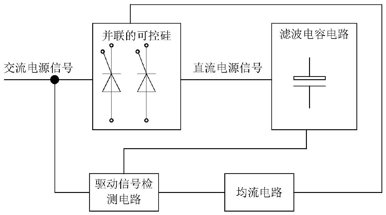
[0021] A first embodiment of the present invention relates to an inverter control circuit. The specific structure is as figure 1 As shown, the inverter control circuit includes: two parallel silicon controlled rectifiers, a filter capacitor circuit, a drive signal detection circuit and a current sharing circuit.

[0022] Two parallel thyr...


PUM


Abstract

The invention relates to the field of frequency converter control and discloses a frequency converter control circuit. Two silicon controlled rectifiers connected in parallel are used for receiving alternating-current power signals and rectifying the alternating-current power signals into direct-current power signals; a filter capacitor circuit is connected with the silicon controlled rectifiers and is used for performing filtering processing on the direct-current power signals; a driver signal detection circuit is connected with the filtering capacitor circuit and used for receiving the alternating-current power signals and outputting driver input signals according to the alternating-current power signals and the filtered direct-current power signals; and a current-sharing circuit is connected with the driver signal detection circuit and the silicon controlled rectifiers, and used for outputting a first driver signal and a second driver signal according to the driver input signals to control the silicon controlled rectifiers to rectify the alternating-current power signals. Therefore, the driver signals can be provided for the silicon controlled rectifiers connected in parallel, and current loads of the silicon controlled rectifiers connected in parallel have high consistency; and the frequency converter control circuit is low in cost, simple in structure, small in size and high in reliability.

Description

technical field [0001] The invention relates to the field of frequency converter control, in particular to a frequency converter control circuit. Background technique [0002] The current frequency converter, welding machine and other products require more and more power. In some occasions, it is difficult for a single SCR used in rectification to meet the power requirements. So it is necessary to use two or more thyristors in parallel to meet the requirements of use. When the thyristors are connected in parallel, if the consistency of the parameters of the drive circuit or the main circuit is not good, the current flowing through each thyristor will be inconsistent. As a result, the load of one thyristor is too small, and the load of the other thyristor is too large, which reduces its life or directly damages it. [0003] The scheme of current sharing transformer can be used to make the loads of parallel thyristors consistent, but this scheme is costly and bulky. In vie...

Claims


Application Information

Patent Timeline
Patent Type & Authority Patents(China)
IPC IPC(8): H02M7/17H02M1/088H02M1/092H02M1/34
CPCH02M1/088H02M1/092H02M1/34H02M7/17
Inventor 杨后跃何栋林张盛张风江
Owner SHANGHAI STEP ELECTRIC
Learn More