Coupled quasi-Z-source direct-current converter

A DC converter, coupled technology, applied in the direction of conversion equipment without intermediate conversion to AC, output power conversion devices, electrical components, etc., can solve the problem of increasing power electronic device losses, low reliability of clamping diodes, power electronics The increase of devices and other problems can improve system efficiency and power density, reduce design, and avoid voltage mutation.

Pending Publication Date: 2022-02-01
STATE GRID ELECTRIC POWER RES INST +5
View PDF0 Cites 0 Cited by
  • Summary
  • Abstract
  • Description
  • Claims
  • Application Information

AI Technical Summary

Problems solved by technology

[0004] Conventional quasi-Z source DC converters still have the following problems: 1. In order to ensure the commutation circuit, clamp diodes are used for unidirectional isolation, which increases the loss of power electronic devices; 2. In medium and high-power high-frequency circuits, the clamp The reliability of diode isolation is very low; 3. In DC conversion, the quasi-Z source converter does not aim at how to offset the influence of the voltage source on the output side in the direct-passing interval of the switch tube, limiting its application in the field of current source; 4. Power electronics The number of devices increases, and the cost of corresponding circuit integration is extremely high

Method used


Image

  • Coupled quasi-Z-source direct-current converter
  • Coupled quasi-Z-source direct-current converter
  • Coupled quasi-Z-source direct-current converter

Examples


Embodiment Construction

[0018] The technical solutions of the present invention will be further described below in conjunction with the accompanying drawings and embodiments.

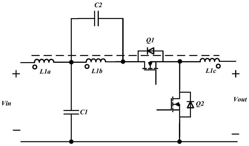
[0019] Such as figure 1 As shown, the coupled quasi-Z source DC converter of the present invention includes two independent DC capacitors, a DC half-bridge consisting of two switching tubes, and a three-winding coupling inductor.

[0020] It specifically includes a first DC capacitor C1, a second DC capacitor C2, an upper switching transistor Q1, a lower switching transistor Q2, a first winding L1a, a second winding L1b, and a third winding L1c. Among them, L1a, L1b, and L1c form a three-winding coupled inductor. The input voltage of the coupled quasi-Z source DC converter is Vin, and the output voltage is Vout.

[0021] The end of the same name of the first winding L1a of the three-winding coupled inductor is connected to the positive pole of the input side of the quasi-Z source DC converter, the other end of the first wind...


PUM


Abstract

The invention discloses a coupled quasi-Z-source direct-current converter. The converter comprises two independent direct-current capacitors, a direct-current half bridge and a three-winding coupling inductor. The direct-current half bridge is composed of two switching tubes. The clamping effect of the diodes is realized by utilizing the electromotive force effect of the two coupling inductors in the quasi-Z-source network, the diodes in the commutation loop are removed, and the circuit reliability is improved. The electromotive force of the output end coupling inductor is utilized to realize mutual abutting between the electromotive force of the output inductor and the voltage source of the output end when the switching tube is directly connected, thereby preventing voltage mutation at two ends of the output inductor and preventing out-of-control caused by overlarge ripple of the output current. By utilizing the effect of the coupling inductance electromotive force of the output end, when the switching tube performs complementary voltage reduction work, the coupling of the inductance enables the equivalent inductance of the output end to be larger, the corresponding output current ripple to be smaller, the design of an output side filter is reduced, and the system efficiency and the power density are improved.

Description

technical field [0001] The invention relates to a converter topology design in the field of power electronics, in particular to a coupled quasi-Z source DC converter. Background technique [0002] Since traditional voltage source converters and current source converters cannot be step-up / step-down converters at the same time, many topologies of Z-source converters or quasi-Z-source converters have been proposed in the industry. At present, the research in the quasi-Z source converter field mainly includes: the control of the quasi-Z source converter, the gain of the quasi-Z source converter, and the combination of the advantages of the quasi-Z source converter and other topologies. [0003] A conventional quasi-Z source DC converter includes two independent inductors, two independent capacitors, a diode, a DC half-bridge, and an output independent inductor. Two independent inductors and two independent capacitors are mainly responsible for the energy transfer of the half-br...

Claims


Application Information

Patent Timeline
IPC IPC(8): H02M3/07H02M1/14
CPCH02M3/07H02M1/143
Inventor 俞普德江小兵杨合民姜辉余谦汪科荣爽张华润王后生陈杰钮向荣
Owner STATE GRID ELECTRIC POWER RES INST
Why Eureka
Try Eureka