Suburban intelligent street lamp
A smart street lamp and suburban technology, applied in the direction of circuit layout, lamp circuit layout, energy-saving control technology, etc., can solve the problems of waste of resources, difficult equipment maintenance, etc., and achieve the effect of practical function, convenient debugging and maintenance, and strong versatility
- Summary
- Abstract
- Description
- Claims
- Application Information
AI Technical Summary
Problems solved by technology
Method used
Image
Examples
Embodiment 1
[0015] In order to further illustrate the technical means and effects adopted by the present invention to achieve the intended purpose, the specific implementation, structural features and effects of the present invention will be described in detail below in conjunction with the accompanying drawings and examples.
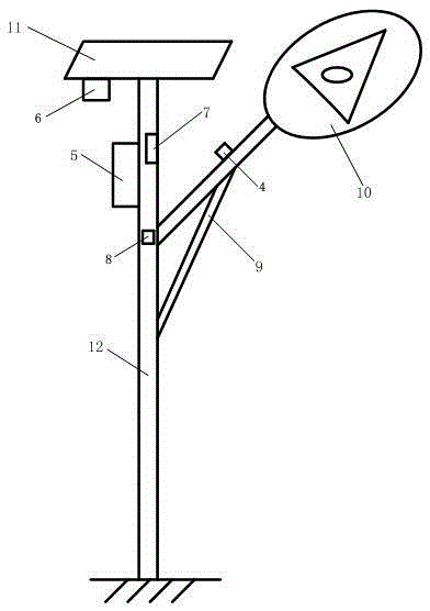
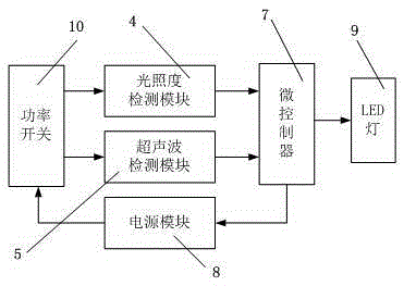
[0016] As shown in Figure 1, a suburban intelligent street lamp of the present invention includes a street lamp pole 1, a lamp stand 2, a wooden board 3, a power module 8, and an LED lamp 9, and is characterized in that it also includes: a microcontroller 7, an illuminance detection module 4, an ultrasonic detection The module 5 and the wireless sending / receiving module 6; wherein, the light frame 2 is installed on the upper half of the light pole 1, and the LED light 9 is installed on the light frame 2; the power module 8 is installed inside the light pole 1, close to the light frame 2; The input end of the power supply module 8 is connected to the mains, and the o...
Embodiment 2
[0020] The microcontroller 7 of the present invention is divided into two types of master and slave. Structurally speaking, the master controller has complete functions, while the slave controller has no ultrasonic detection and wireless transmission functions. Since the effective communication distance of the wireless sending / receiving module 6 is 150-200 meters, a host controller is installed every 100 meters, and a slave controller is installed on each street lamp between the two host controllers. During work, the microcontroller 7 determines whether it is daytime or night according to the signal fed back by the illuminance sensor. When the light is insufficient, the microcontroller 7 controls the power switch 10 to be turned on. The delay time of the circuit is about 5 hours, and the vehicle detection and wireless control will not be performed when the timing time is not up. That is to say, the system considers the first 5 hours after dark to be normal activity time, and n...
Embodiment 3
[0022] Considering the characteristics of the installation and maintenance process and personnel structure in the transportation industry, the wireless sending / receiving module 6 in the present invention adopts the communication mode of PT2262 and PT2272. This is a pair of wireless remote control transmitter / receiver chips with address and data encoding functions. In the circuit, a surface acoustic resonator is used instead of a traditional LC oscillator, and an antenna with a characteristic impedance of 50 ohms is connected. Through experimental verification, the work is stable and The communication is reliable, and the outdoor distance can reach 150 meters, which fully meets the design requirements. The wireless signal spreads around in the space. In order to prevent affecting the street lamps on the opposite side of the road or other nearby roads, it is divided into four modes according to the north-south and east-west directions of the road. A two-digit dial switch is set o...
PUM
 Abstract
Description
Claims
Application Information
 - R&D
- Intellectual Property
- Life Sciences
- Materials
- Tech Scout
- Unparalleled Data Quality
- Higher Quality Content
- 60% Fewer Hallucinations
Browse by: Latest US Patents, China's latest patents, Technical Efficacy Thesaurus, Application Domain, Technology Topic, Popular Technical Reports.
© 2025 PatSnap. All rights reserved.Legal|Privacy policy|Modern Slavery Act Transparency Statement|Sitemap|About US| Contact US: help@patsnap.com


