Boiler for beverage extracting device

A technology for extraction equipment and boilers, which is applied in the field of boilers for beverage extraction equipment, can solve the problems of inconspicuous lifting effect, speed up the heating speed of water pipes, and speed up the heat transfer speed of heating pipes, so as to ensure heating efficiency, increase heating paths, and increase heating the effect of time

Active Publication Date: 2017-05-17
NINGBO SEAVER ELECTRIC APPLIANCE
View PDF14 Cites 11 Cited by
  • Summary
  • Abstract
  • Description
  • Claims
  • Application Information

AI Technical Summary

Problems solved by technology

Because the water pipe is spirally arranged in the furnace wall, and the heating pipe is spirally arranged in the furnace wall outside the water pipe, the heat of the heating pipe is transferred to the water pipe through the furnace wall, which increases the distance between the heating pipe and the furnace wall. The contact area speeds up the heat transfer speed of the heating pipe, and also speeds up the contact area between the furnace wall and the water pipe, speeding up the heating speed of the water pipe, and because the water pipe is a spiral structure, the water has to go through a relatively long time from the water inlet to the water outlet. The heating pipe can ensure that the water entering the furnace body from the water inlet reaches the temperature required for brewing coffee at the water outlet. However, there is a water pipe between the heating part of the heating boiler and the water flow, which is indirect heating. The first solution is direct heating. Compared with the first solution, the heating method can improve the heating efficiency a little, but the improvement effect is not obvious
[0005] Furthermore, the heating boiler in the existing coffee machine only plays the role of heating water, and does not have the compacting function of compressing the capsule to form the extraction chamber. This compacting function also requires an additional arrangement of a piston in the coffee machine structure formation

Method used


Image

  • Boiler for beverage extracting device
  • Boiler for beverage extracting device
  • Boiler for beverage extracting device

Examples


Embodiment Construction

[0023] The present invention will be further described in detail below in conjunction with the accompanying drawings and embodiments.

[0024] Such as Figure 1~6 Shown is a preferred embodiment of the present invention.

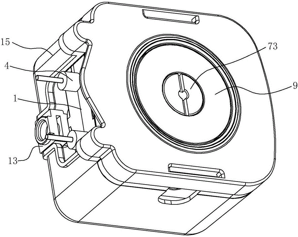
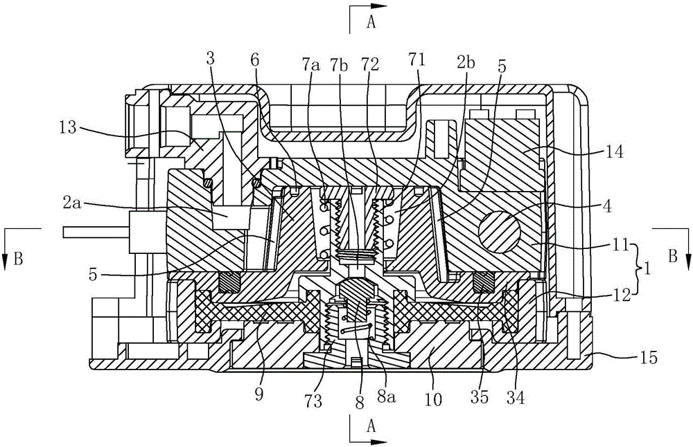
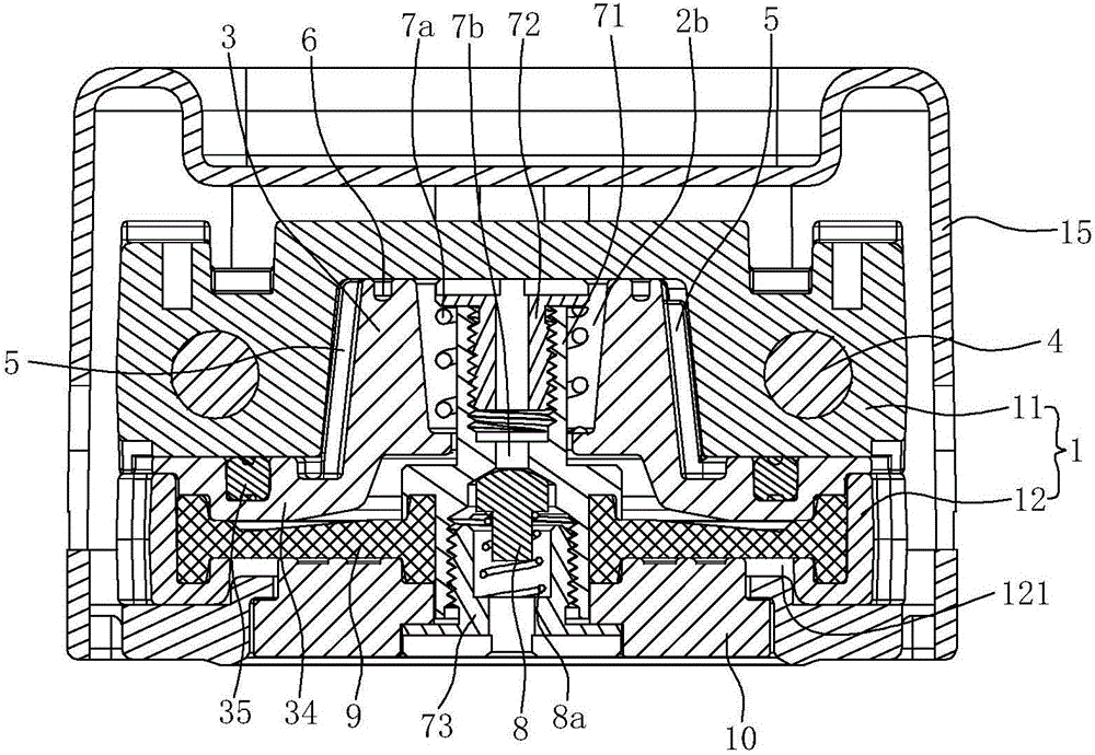
[0025] A boiler for beverage extraction equipment, including a boiler body with a water inlet channel 2a and a water outlet channel 2b, the boiler body is built with a heating tube 4, the heating tube 4 is generally an electric heating tube, and the two ends of the heating tube 4 protrude from the boiler body to form The terminal and the pot body are also provided with a heating runner.

[0026] The boiler body includes an outer boiler body 1 and a boiler core 3. The outer boiler body 1 and boiler core 3 are aluminum die-casting parts, and the outer boiler body 1 is coated on the periphery of the boiler core 3. The outer boiler body 1 is composed of an upper boiler body 11 and a lower boiler body. Boiler body 12 is fixedly connected to form, and the bottom...


PUM


Abstract

The invention relates to a boiler for a beverage extracting device. The boiler comprises a boiler body, a heating pipe and a heating runner, wherein the boiler body is equipped with a water inlet channel and a water outlet channel; the boiler is characterized in that the boiler body comprises an outer boiler body and a boiler core; the heating runner comprises an annular runner and a transition runner; the annular runner is arranged along the outer peripheral wall of the boiler core; the transition runner is arranged on the top surface of the boiler core; the initial end of the annular runner is communicated with the water inlet channel; the terminal end of the annular runner is communicated with an inlet of a transition channel; an outlet of the transition channel is communicated with the inlet of the water outlet channel; the annular runner is composed of a plurality of mutually connected upstream runners and downstream runners; one downstream runner is arranged between two adjacent upstream runners; one upstream runner is arranged between the two adjacent downstream runners. The whole heating route is greatly increased by water flow, and meanwhile, the annular runner and the transition runner are directly arranged between the outer boiler body and the boiler core and the heating manner is in direct heating, so that the heating efficiency of the boiler is further guaranteed and the boiler can achieve the effect of quick heating (instant heating).

Description

technical field [0001] The present invention relates to a water heating device, in particular to a boiler for beverage extraction equipment, wherein the beverage extraction equipment can be a coffee machine or similar equipment. Background technique [0002] The heating boiler in the existing coffee machine has two structural forms. [0003] The first type: The heating boiler is composed of an upper boiler body and a lower boiler body. The upper boiler body and the lower boiler body are connected together by screws, and a seal is provided at the joint of the outer ring between the upper boiler body and the lower boiler body. There is a water inlet channel on the upper boiler body, an electric heating tube is provided inside the lower boiler body, a spiral heating flow channel is provided on the upper surface of the lower boiler body, and a water outlet is provided at the center of the lower boiler body. channel, the water outlet channel axially runs through the lower bottom...

Claims


Application Information

Patent Timeline
Patent Type & Authority Applications(China)
IPC IPC(8): A47J31/54A47J31/46
CPCA47J31/46A47J31/542A47J31/545
Inventor 汪天平
Owner NINGBO SEAVER ELECTRIC APPLIANCE
Why Eureka
Try Eureka