
Electrical sterilization device for machinery

A disinfection device and electrical technology, applied in the direction of disinfection, water supply equipment, sanitary equipment for toilets, etc., can solve the problems of operator injury, shorten the service life of the disinfection device, and damage the mechanical parts of the disinfection device, so as to improve the effect and improve The effect of the automation effect

Inactive Publication Date: 2017-05-17
ZHONGSHAN FRED MACHINERY CO LTD
View PDF4 Cites 0 Cited by
  • Summary
  • Abstract
  • Description
  • Claims
  • Application Information

AI Technical Summary

Problems solved by technology

[0003] Existing disinfection devices are manually controlled disinfection time, the staff need to wait for the corresponding time after opening, and then manually closed, the staff in the whole process of disinfection can not be too far away from the disinfection device, wasting the time of the staff, and When the staff forget to close the disinfection device, the long-term high temperature in the disinfection device will damage the mechanical parts in the disinfection device and shorten the service life of the disinfection device. The cabinet door of the existing disinfection device can be opened directly. When opening the cabinet door due to curiosity and other reasons, and performing related incorrect operations, one is easy to damage the disinfection device, and the other is that the high temperature of the disinfection device is easy to burn the skin of the operator and cause injury to the operator. When the staff place and take out the sterilized machinery, it is inconvenient to place and take out the mechanical equipment placed at a high place

Method used


Image

  • Electrical sterilization device for machinery
  • Electrical sterilization device for machinery
  • Electrical sterilization device for machinery

Examples


Embodiment Construction

[0023] In order to make the technical means, creative features, goals and effects achieved by the present invention easy to understand, the present invention will be further described below in conjunction with specific embodiments.

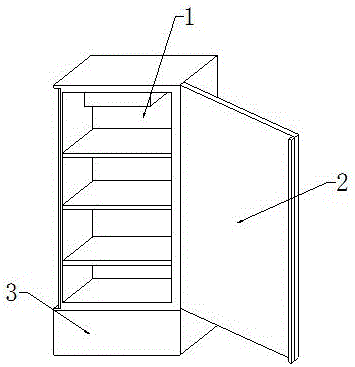
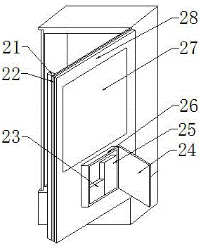
[0024] see Figure 1-Figure 4 , the present invention provides a technical solution: an electrical disinfection device for machinery, comprising a disinfection cabinet assembly 1, a cabinet door assembly 2 and an auxiliary tool assembly 3, the upper end of the auxiliary tool assembly 3 is equipped with a disinfection cabinet assembly 1, and the front end of the disinfection cabinet assembly 1 A cabinet door assembly 2 is installed.

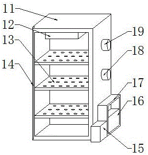
[0025] The disinfection cabinet assembly 1 comprises a cabinet body 11, an infrared heating lamp 12, a placement plate 13, an iron block 14, a timing switch 15, a battery one 16, a casing one 17, an air outlet 18 and a nitrogen inlet 19, and the placement plate 13 is provided with three, Three placement boards 13 are...


PUM


Abstract

The invention provides an electrical sterilization device for machinery. The electrical sterilization device comprises a cabinet body, an infrared heating lamp, a timing switch, a storage battery I, a box body I, an air inlet, a nitrogen inlet, an electromagnet, a power switch, a storage battery II, a box body II and a cabinet door, wherein the infrared heating lamp is arranged on the top end of the inner part of the cabinet body, the air inlet and the nitrogen inlet are formed in the right end of the cabinet body, the nitrogen inlet is arranged at the upper side of the air inlet, the box body I is arranged at the lower side of the air inlet, the storage battery I is arranged in the box body I, and the timing switch is arranged on the front end of the box body I, so that the automation effect is increased through the design; the electromagnet is arranged on the left end of the cabinet door, the box body II is fixedly arranged on the right end of the cabinet door, the power switch and the storage battery II are equipped in the box body II, and the power switch is arranged on the front end of the storage battery II, so that the safety is increased through the design. According to the electrical sterilization device provided by the invention, the use is convenient, the operation is easy, the safety is good, and the working efficiency is increased.

Description

technical field [0001] The invention is an electrical disinfection device for machinery, which belongs to the field of disinfection equipment. Background technique [0002] With the development of science and technology, more and more mechanical products have been invented. In order to ensure the safety and health of people, the machinery used for diet and medical treatment must be sterilized before use. The electrical disinfection device for machinery is used A device for disinfecting and sterilizing machinery. [0003] Existing disinfection devices are manually controlled disinfection time, the staff need to wait for the corresponding time after opening, and then manually closed, the staff in the whole process of disinfection can not be too far away from the disinfection device, wasting the time of the staff, and When the staff forget to close the disinfection device, the long-term high temperature in the disinfection device will damage the mechanical parts in the disinfe...

Claims


Application Information

Patent Timeline
IPC IPC(8): A61L2/04A61L2/24A61L2/26
CPCA61L2/04A61L2/24A61L2/26
Inventor 卢冬平王娜高利平
Owner ZHONGSHAN FRED MACHINERY CO LTD
Learn More