Cleaning equipment for petroleum pipelines

A technology for cleaning equipment and oil pipelines, applied in the directions of cleaning hollow objects, cleaning methods and utensils, chemical instruments and methods, etc., can solve the problems of inability to adjust, single cleaning brush, poor cleaning effect, etc., and achieve the effect of improving the cleaning effect

Inactive Publication Date: 2017-05-17
德阳瀚枫科技有限公司
View PDF5 Cites 2 Cited by
  • Summary
  • Abstract
  • Description
  • Claims
  • Application Information

AI Technical Summary

Problems solved by technology

The radius of the cleaning device of the existing oil pipeline cleaner is fixed, and cannot be adjusted according to the pipelines with different inner diameters. At the same time, the cleaning brush is single, and the cleaning effect is poor.

Method used


Image

  • Cleaning equipment for petroleum pipelines
  • Cleaning equipment for petroleum pipelines
  • Cleaning equipment for petroleum pipelines

Examples


Embodiment 1

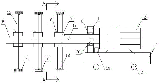
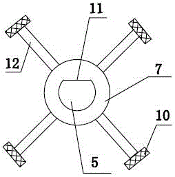
[0020] like figure 1 , figure 2 As shown, a kind of cleaning equipment for petroleum pipelines comprises a base 1, a motor 2, a column 4, a rotating shaft 5 and a cleaning device. A bearing 6 is arranged in the hole, and the cleaning device is installed on the rotating shaft 5, and the rotating shaft 5 is connected to the output shaft of the motor 2 through (or passing through) the bearing 6. The cleaning device of the present invention includes a connecting plate 7 and a connecting rod 12. The connecting disc 7 is sleeved on the rotating shaft 5 and fixed with the rotating shaft 5. There are at least two connecting discs 7, which are evenly sleeved on the rotating shaft 5. The outer circumference of the connecting rod 12 and the connecting disc to the connection (such as figure 2 shown), and evenly distributed along the outer circumference of the connecting plate 7 (because there are multiple connecting rods 12, generally 4-8); Effective cleaning of pipelines with seriou...

Embodiment 2

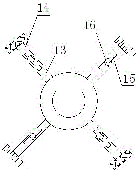
[0025] like figure 1 and image 3 As shown, a kind of cleaning equipment for petroleum pipelines comprises a base 1, a motor 2, a column 4, a rotating shaft 5 and a cleaning device. A bearing 6 is arranged in the hole, and the cleaning device is installed on the rotating shaft 5, and the rotating shaft 5 is connected to the output shaft of the motor 2 through (or passing through) the bearing 6. The cleaning device of the present invention includes a connecting plate 7 and a connecting rod 12. The connecting disc 7 is sleeved on the rotating shaft 5 and fixed with the rotating shaft 5. There are at least two connecting discs 7, which are evenly sleeved on the rotating shaft 5. The connecting rod 12 includes a fixed plate 13 and a guide rod 14. The fixed plate 13 is plate-shaped, and the fixed plate 13 is radially connected with the outer circumference of the connection plate (such as image 3 shown), and evenly distributed along the outer circumference of the connection plate...


PUM


Abstract

The invention discloses cleaning equipment for petroleum pipelines. The cleaning equipment comprises a base, a motor, a stand column, a rotary shaft and a cleaning device. The cleaning device comprises connecting discs and connecting rods. The connecting discs are arranged on the rotary shaft in a sleeving manner. The connecting rods are in radial connection with the outer circumferences of the connecting discs and are evenly distributed along the outer circumferences of the connecting discs. A steel wire brush is arranged at the end of each connecting rod. A cleaning liquid tank is arranged on the base. A nozzle is arranged at the end of each connecting rod. The cleaning liquid tank is connected with the nozzles through a water pipe. According to a cleaner, the different cleaning brushes are mounted on the cleaning device, cleaning liquid is used in cooperation, and therefore a better cleaning effect is achieved.

Description

technical field [0001] The invention relates to the technical field of petrochemical machinery, in particular to a cleaning device for petroleum pipelines. Background technique [0002] For pipelines that have been used for a long time, the solidification of oil sludge and rust in the pipeline will cause the diameter of the original pipeline to become smaller; the sludge in the pipeline will produce hydrogen sulfide gas, which will cause environmental pollution and easily cause explosion; the acid and alkali substances in the waste water will easily corrode the pipeline wall; Unscheduled removal of foreign matter in the pipeline will cause pipeline blockage; pipeline cleaning is the process of using chemical or physical methods to remove dirt on the inner surface of the pipeline to achieve the purpose of cleaning and ensure that the inner surface of the pipeline returns to its original surface material. The radius of the cleaning device of the existing petroleum pipeline cle...

Claims


Application Information

Patent Timeline
IPC IPC(8): B08B9/051B08B9/032
CPCB08B9/051B08B9/0321B08B9/0323
Inventor 张紫娟
Owner 德阳瀚枫科技有限公司
Why Eureka
Try Eureka