Die cover structure for welding die

A mold cover and cover body technology, applied in welding equipment, auxiliary welding equipment, welding/cutting auxiliary equipment, etc., can solve the problems of ineffective removal of smoke, unsatisfactory use effect, etc., to achieve convenient fixing and detachment, and good cushioning Action, efficient effect

Active Publication Date: 2017-05-17
宁波高新区远创科技有限公司
View PDF20 Cites 2 Cited by
  • Summary
  • Abstract
  • Description
  • Claims
  • Application Information

AI Technical Summary

Problems solved by technology

However, the mold cannot effectively remove the fume generated during the welding process

Method used


Image

  • Die cover structure for welding die
  • Die cover structure for welding die
  • Die cover structure for welding die

Examples


Embodiment Construction

[0035] The present invention will be further described in detail below in conjunction with the accompanying drawings and embodiments.

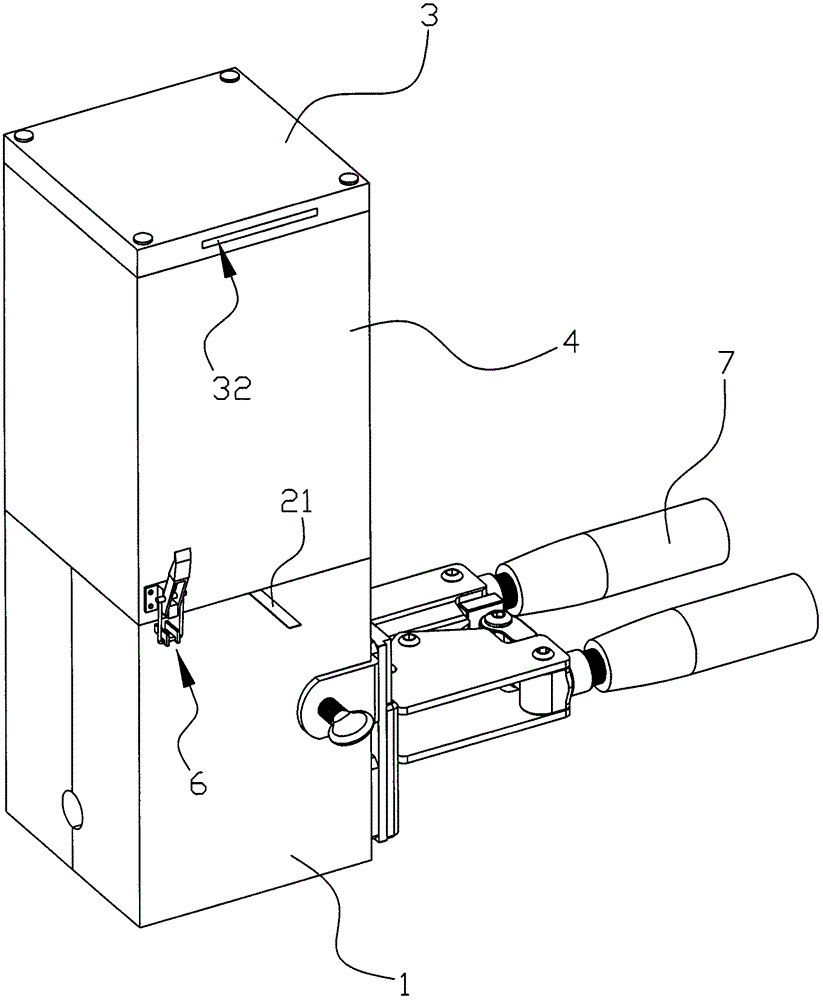
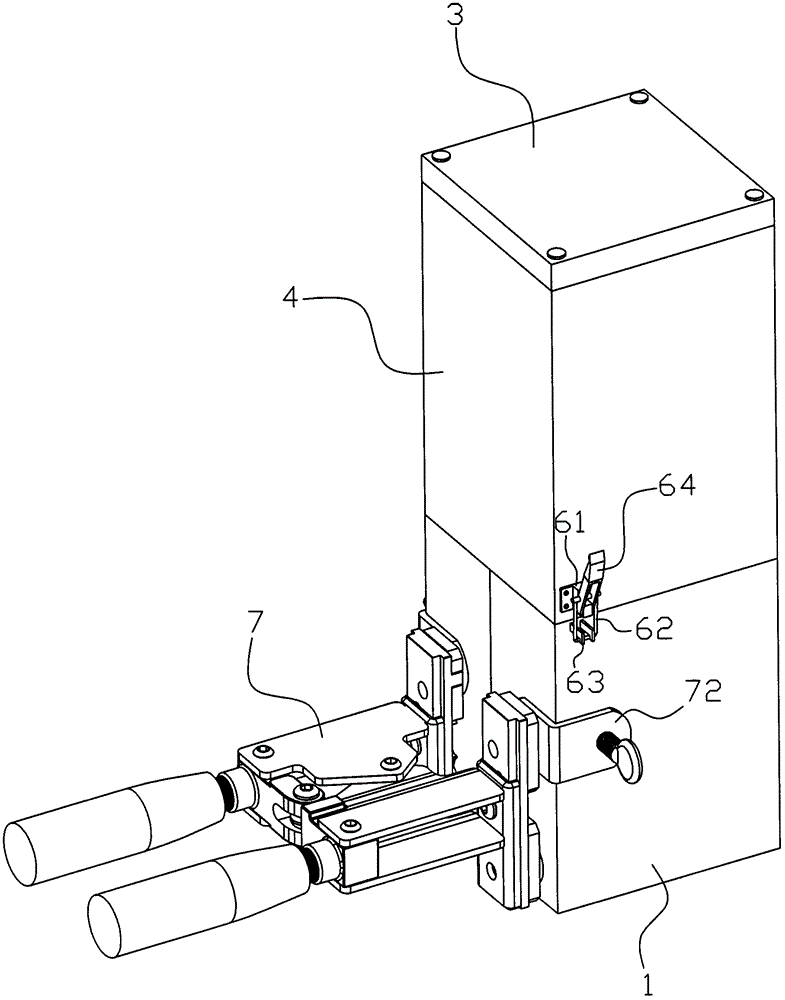
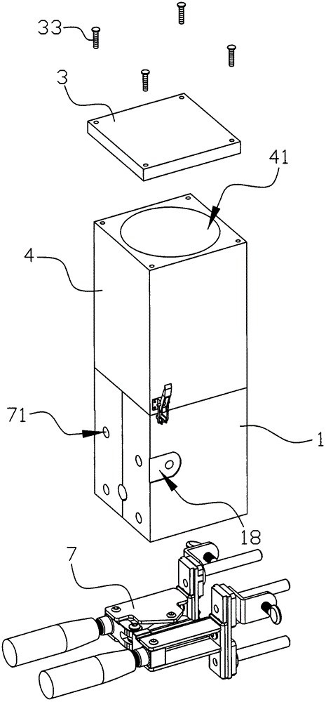
[0036] Such as Figure 1 to Figure 11 As shown, the mold cover structure of the welding mold of the present embodiment includes a mold cover shell, and a vent cavity 41 is arranged in the mold cover shell, and the vent cavity 41 communicates with the outside world through the air outlet 32. The mold cover shell The ventilation cavity 41 in the body includes a filter area and an air outlet 32 ​​that can filter and cool down from bottom to top. 32 communicate with each other, and the air outlet 32 ​​is located on the side of the mold cover housing top.

[0037] There are N filter areas, and N is a natural number greater than or equal to 2; when N is a natural number 2, the filter area includes a metal wire filter area 46 and an organic polymer filamentary filter area 47, and the metal wire filter area 46 is connected with an organic filter area...


PUM


Abstract

The invention discloses a die cover structure for a welding die. The die cover structure comprises a die cover shell. A ventilation cavity is formed in the die cover shell. The ventilation cavity communicates with the outside through an air outlet. The ventilation cavity in the die cover shell comprises a filtering area and an air outlet which are arranged from bottom to top. The lower portion of the filtering area communicates with a melting cavity in the die body, and the upper portion of the filtering area communicates with the air outlet. The air outlet is located in the side face of the upper portion of the die cover shell. The die cover structure has the beneficial effects that the filtering area can conduct filtering and cooling, the smoke removing effect is good, smoke generated by welding needs to pass through the filtering area and then gets away from the die from the air outlet, filtering is sufficient, and the environment is better protected; a partition plate is arranged in a die cover and can separate the filtering area provided with different kinds of filtering filler, multi-layer filtering and multi-time filtering are achieved, and the smoke filtering effect is further improved; the die cover is divided into an upper cover body and a lower cover body, the filtering filler in the filtering area is replaced conveniently, and die cover cleaning is also convenient; and a sealing structure is arranged on the bottom face of a ring-shaped salient pole, and it is ensured that smoke enters the filtering area from the top of the sealing structure.

Description

technical field [0001] The invention relates to the technical field of welding mold production, in particular to a mold cover structure of a welding mold. Background technique [0002] An existing patent No. CN201310073329.6, a Chinese invention patent titled "Welding Mold", discloses a welding mold, including a mold body and a mold cover. The mold is provided with a reaction cavity, a drainage groove, and a welding cavity. The bottom surface of the reaction chamber at the top of the drainage tank is provided with a metal spacer that prevents the metal powder in the reaction chamber from falling into the welding chamber before the reaction and has a melting point lower than that of metal copper. The top surface of the mold body is provided with a fire bar The insertion slot is characterized in that: the bottom surface of the mold cover is provided with a ventilation cavity, and the ventilation cavity communicates with the cavity of the upper part of the mold cover that can p...

Claims


Application Information

Patent Timeline
IPC IPC(8): B23K37/00
CPCB23K37/00
Inventor 何迎春
Owner 宁波高新区远创科技有限公司
Why Eureka
Try Eureka