Point welding fixture for rotor ventilating slot piece and ventilating slot strip and using method of point welding fixture

A technology of ventilation slots and rotors, applied in manufacturing tools, welding equipment, welding equipment, etc., can solve problems such as increased rework costs, reduced work efficiency, and weak solder joints, so as to improve manufacturing quality, work efficiency, and improve points The effect of welding quality

Active Publication Date: 2017-05-17
ZHENJIANG ZHONGCHUAN XIANDAI GENERATING EQUIP CO LTD
View PDF11 Cites 4 Cited by
  • Summary
  • Abstract
  • Description
  • Claims
  • Application Information

AI Technical Summary

Problems solved by technology

For example, a certain type of rotor ventilation slot 10 requires that the central line of the boss 201 of 48 ventilation slots 20 uniformly distributed in the radial direction shall take the diameter of the center circle of Φ558mm as the assembly reference, and the diameter tolerance of Φ558mm must be within ±0.20mm. The ventilation groove bar 20 after the spot welding special fixture spot welding can't meet this requirement
[0003] The existing spot welding method of the rotor ventilation slots and the ventilation slots adopts the ventilation slots placed on the upper side of the rotor ventilation slots, and the spot welding head of the spot welding machine presses down the ventilation slots to spot-weld it on the rotor ventilation slots. The thickness of the ventilation slots is greater than that of the rotor ventilation slots, and due to the material of the two, the current cannot be effectively transmitted, resulting in weak solder joints and the ventilation slots are easy to fall
In addition, the existing spot welding method uses manual visual inspection to advance the rotor ventilation slots for spot welding at intervals, which cannot guarantee that the spacing of the solder joints meets the design requirements. The above two defects seriously affect the manufacturing quality of the rotor ventilation slots and increase rework. cost, reduced work efficiency

Method used


Image

  • Point welding fixture for rotor ventilating slot piece and ventilating slot strip and using method of point welding fixture
  • Point welding fixture for rotor ventilating slot piece and ventilating slot strip and using method of point welding fixture
  • Point welding fixture for rotor ventilating slot piece and ventilating slot strip and using method of point welding fixture

Examples


Embodiment Construction

[0028] The present invention will be further described below in conjunction with drawings and embodiments.

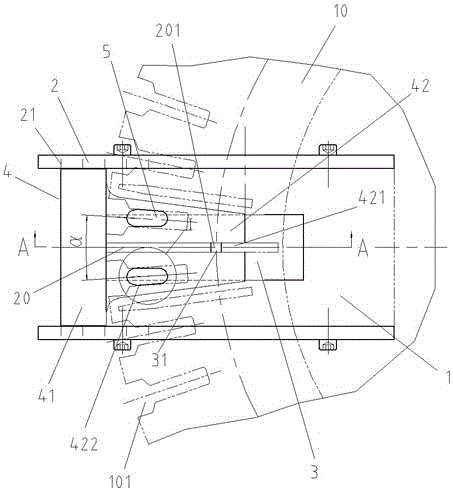
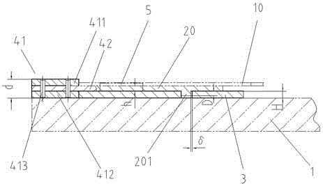
[0029] Such as Figure 2 ~ Figure 4 As shown, the spot welding fixture of the rotor ventilation slots and ventilation slots in this embodiment includes a spot welding machine copper base plate 1, a pair of moving guide rails 2, a copper backing plate 3, a rotor ventilation slot positioning piece 4 and two positioning blocks 5. The moving guide rail 2 is strip-shaped, and its longitudinal lower part is respectively fixed on the longitudinal two sides of the copper base plate 1 of the spot welding machine by fastening screws. The rotor ventilation slot positioning piece 4 is T-shaped, including a rear positioning plate 41 and a ventilation slot positioning plate 42 vertically extending outward from the middle of the rear positioning plate 41. The ventilation slot positioning plate 42 is provided with a ventilation slot in the longitudinal center. The width of the bar 20 ...


PUM


Abstract

The invention discloses a point welding fixture for a rotor ventilating slot piece and a ventilating slot strip. The point welding fixture comprises a point welding machine copper bottom plate, a pair of moving guide rails, a copper base plate, a rotor ventilating slot piece positioning component and two positioning blocks. A positioning groove is formed in the longitudinal center of a ventilating slot strip positioning plate. The two ends of a rear positioning plate are movably connected with the inner sides of the pair of moving guide rails. Positioning block grooves are formed in the two sides of the positioning groove correspondingly. The bottom surfaces of the positioning blocks are supported on the upper side face of the point welding machine copper bottom plate. The copper base plate is located between the rotor ventilating slot piece positioning component and the point welding machine copper bottom plate. A using method of the point welding fixture comprises the following steps that a boss of the ventilating slot strip is downwards embedded into the positioning groove, two adjacent notches of the rotor ventilating slot piece are embedded into the two positioning blocks, the rotor ventilating slot piece and the ventilating slot strip are pressed downwards and point-welded through a point welding head, and the rotor ventilating slot piece positioning component and the rotor ventilating slot piece on the rotor ventilating slot piece positioning component are pushed to complete point welding point by point. By adoption of the point welding fixture for the rotor ventilating slot piece and the ventilating slot strip and the using method of the point welding fixture, the manufacturing quality of the rotor ventilating slot piece is improved, the manufacturing cost is reduced, and the working efficiency is improved.

Description

technical field [0001] The invention relates to a spot welding tool for a rotor ventilation slot of an excitation generator, in particular to a spot welding tool and a spot welding method for a rotor ventilation slot and a ventilation slot bar, and belongs to the technical field of motor manufacturing. Background technique [0002] Such as figure 1 As shown, the rotor ventilation slots 10 are fixed on both ends of the rotor core, and dozens of notches 101 for ventilation and cooling are evenly distributed on the edges, and radially between every two adjacent notches 101 are also provided. The ventilation slots 20 whose thickness is greater than that of the rotor ventilation slots 10 are divided into three types of specifications with different lengths. Arranged spot welding spots are fixed on the rotor ventilation slots 10 . When the excitation generator rotor is assembled, the rotor ventilation slots 10 at both ends use the boss 201 as the assembly reference. For example...

Claims


Application Information

Patent Timeline
Patent Type & Authority Applications(China)
IPC IPC(8): B23K37/04B23K31/02
CPCB23K31/02B23K37/0443
Inventor 李进
Owner ZHENJIANG ZHONGCHUAN XIANDAI GENERATING EQUIP CO LTD
Why Eureka
Try Eureka