Adjustable pad structure used in high-temperature side bearing cavity of engine

A technology for adjusting pads and engines, which is applied in the directions of engine lubrication, engine components, turbine/propulsion device lubrication, etc. It can solve the problem of increasing the difficulty of selecting bearing radial oil clearance, affecting the safety and life of the engine, and the inner ring of the bearing runway. Temperature rise and other issues can be avoided to avoid the risk of abrasion, reduce the consumption of lubricating oil, and reduce the processing cost

Active Publication Date: 2017-05-17
中科航星科技股份有限公司
View PDF5 Cites 4 Cited by
  • Summary
  • Abstract
  • Description
  • Claims
  • Application Information

AI Technical Summary

Problems solved by technology

This high-temperature heat conduction effect will cause the temperature of the inner ring of the bearing runway to rise, deteriorating the working conditions of the bearing
At the same time, the rise in temperature will increase the difficulty of selecting the interference of the inner ring and the selection of the radial oil clearance of the bearing when the bearing is assembled in a cold state.
Therefore, how to solve the problem of high working temperature of the bearing inner ring is an important technical issue that affects the safety and life of the engine
[0004] In addition, when ground gas turbines and aero-engines are started in a cold state on the ground, the bearing cavity is often in a state of "dry oil pool". The pre-supply of lubricating oil in the starting state is also a prominent and difficult technical problem

Method used


Image

  • Adjustable pad structure used in high-temperature side bearing cavity of engine
  • Adjustable pad structure used in high-temperature side bearing cavity of engine
  • Adjustable pad structure used in high-temperature side bearing cavity of engine

Examples


Embodiment Construction

[0023] In order to make the object, technical solution and advantages of the present invention clearer, the present invention will be further described in detail below in conjunction with the accompanying drawings and specific embodiments. It should be noted that the following examples are for explaining the present invention and the present invention is not limited to the following examples.

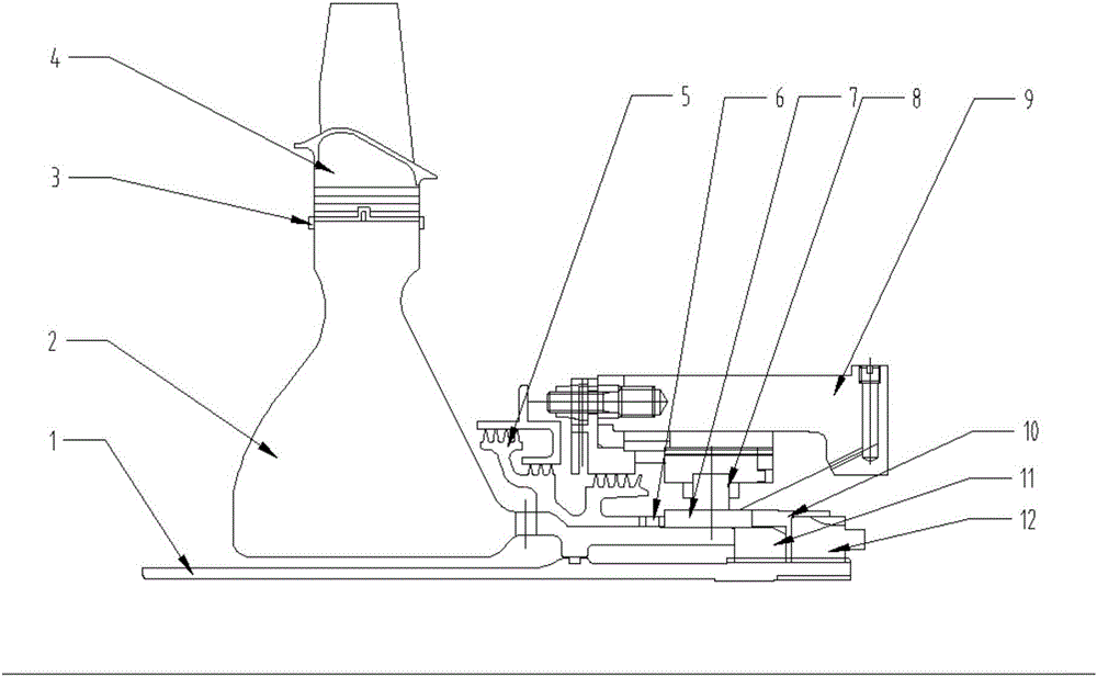
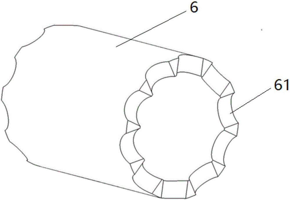
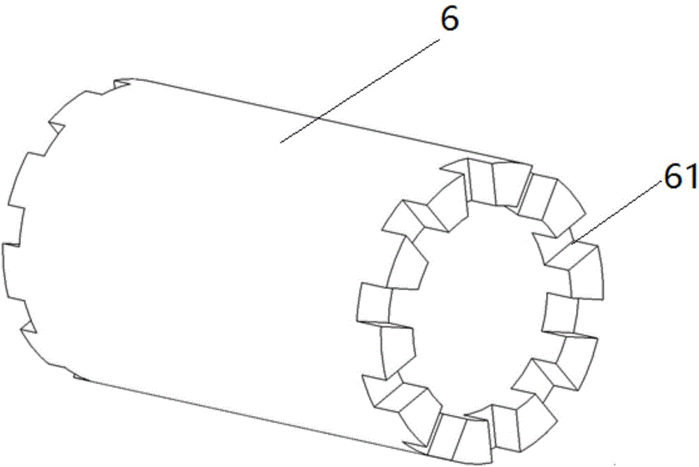
[0024] Such as figure 1 As shown, this embodiment is a design scheme of using the adjusting pad structure of the present invention in the high-pressure rear fulcrum bearing chamber of the aeroengine. In this embodiment, a high-pressure rear fulcrum rod bearing 8, an adjustment pad 6, and a sealing grate ring 5, which are sleeved on the high-pressure turbine shaft 1, are arranged in the bearing chamber on the high-temperature side of the engine, and the high-pressure rear fulcrum rod bearing 8 is further arranged on the In the bearing seat 9, an oil supply nozzle assembly is set on the ...


PUM


Abstract

The invention relates to an adjustable pad structure used in a high-temperature side bearing cavity of an engine, and the adjustable pad structure can be widely applied to such fields as ground-based gas turbines, aero-engines and the like. A bearing, an adjustable pad and a sealing labyrinth ring which are arranged on a turbine shaft in a sleeving manner are arranged in the high-temperature side bearing cavity of the engine, one end surface of the adjustable pad is propped against the sealing labyrinth ring, the other end surface of the adjustable pad is propped against a bearing track inner ring, and a hot-end turbine rotating part is arranged on the inner side of the sealing labyrinth ring. The adjustable pad structure is characterized in that a plurality of toothed grooves are formed at least in the end surface, propped against the bearing track inner ring, of the adjustable pad. Compared with a traditional adjustable pad, the adjustable pad structure provided by the invention has the advantages of simple structure, low processing cost and complete function, can achieve dual effects of reducing heat conduction of high-temperature parts and providing lubricating oil required by cold start of the engine, can control the temperature of the bearing inner ring more effectively and meets the demand for supplying the lubricating oil required by cold start of the engine.

Description

technical field [0001] The invention relates to an adjusting pad structure used in high temperature side bearing cavities in the fields of ground gas turbines, aeroengines and the like. Utilizing various concave tooth-shaped structures on the end surface of the adjusting pad structure, the cold start-up supply of lubricating oil in the high temperature side bearing cavity and the low temperature control of the inner raceway of the bearing can be realized. Background technique [0002] The pre-supply of cold lubricating oil in the bearing chamber of high-speed rotating bearings and the temperature control of the inner ring runway of the bearing are two engineering problems of great significance in the fields of ground gas turbines and aeroengines. [0003] In the structural design of gas turbines and aero-engines, the axial and radial clearances of rotating parts are realized by various adjustment pad structures pressed on the rotating shaft, which is a low-cost, high-efficie...

Claims


Application Information

Patent Timeline
Patent Type & Authority Applications(China)
IPC IPC(8): F02C7/06
CPCF02C7/06
Inventor 杜强刘军柳光杨晓洁王沛徐庆宗刘红蕊
Owner 中科航星科技股份有限公司
Why Eureka
Try Eureka