Connecting structure for impeller and high-speed shaft of steam compressor

A technology of steam compressor and connection structure, applied in mechanical equipment, machine/engine, liquid fuel engine, etc., can solve the problems affecting the long-term stable operation of the unit, hidden dangers, no sealing method, etc., to prevent water vapor from entering the contact surface , improve security, ensure the effect of connection

Pending Publication Date:
View PDF6 Cites 3 Cited by
  • Summary
  • Abstract
  • Description
  • Claims
  • Application Information

AI Technical Summary

Problems solved by technology

[0007] Because the working fluid of the steam compressor is water vapor, if there is no effective seal between the contact surface between the impeller and the high-speed shaft, the water vapor will corrode the high-speed shaft and affect the long-term stable operation of the unit, which is a relatively large safety hazard. There is no particularly good sealing method

Method used


Image

  • Connecting structure for impeller and high-speed shaft of steam compressor
  • Connecting structure for impeller and high-speed shaft of steam compressor
  • Connecting structure for impeller and high-speed shaft of steam compressor

Examples


Embodiment Construction

[0018] The technical solutions of the embodiments of the present invention will be clearly and completely described below in conjunction with the accompanying drawings of the present invention.

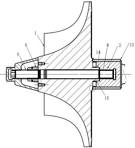
[0019] like Figure 1~4 As shown, a connection structure of a steam compressor impeller and a high-speed shaft disclosed in the present invention includes an impeller 1 and a high-speed shaft 2, the contact surface 3 of the high-speed shaft 2 has an internal thread fixing hole 4, and the impeller and the high-speed shaft The pull rod 5 passes through the inner hole of the impeller 1 and is fixed in the internally threaded fixing hole 4, and the tail end of the pull rod 5 is locked on the outside of the impeller through a lock nut 6 to ensure that the impeller and the high-speed shaft are axially tightly connected.

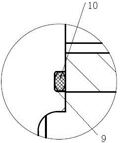
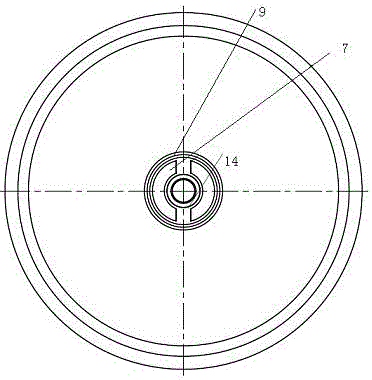
[0020] Specifically, the center of the contact surface 7 of the impeller 1 has a keyway 14, and a ring of sealing grooves 9 is provided on the contact surface 7 outside th...


PUM


Abstract

The invention discloses a connecting structure for an impeller and a high-speed shaft of a steam compressor. The connecting structure comprises the impeller and the high-speed shaft. An internal-thread fixing hole is formed in a contact surface of the high-speed shaft, and the impeller and the high-speed shaft are tightly connected in the axial direction through the mode that a pull rod penetrates through an impeller inner hole to be fixed to the high-speed shaft and a locking nut is arranged at the tail end of the pull rod for locking. A contact surface of the impeller is provided with two symmetrical key grooves, the contact surface of the high-speed shaft is provided with two keys matched with the key grooves, and torque is transmitted through matching of the key grooves and the keys when the high-speed shaft and the impeller are connected.

Description

technical field [0001] The invention relates to the field of steam compressors, in particular to a connection structure between a steam compressor impeller and a high-speed shaft. Background technique [0002] The steam compressor is the key equipment to increase the steam temperature and pressure in the MVR evaporation system. In the MVR evaporation system, the steam compressor is used as the core component to realize the recompression of the secondary steam in the MVR system, increase the pressure and temperature of the secondary steam, and then enter the heat exchanger to heat the material to achieve the purpose of saving raw steam. Its working principle is to increase the pressure and temperature of the steam through the high-speed impeller. [0003] For steam compressors, the reliable connection between the impeller and the high-speed shaft is the basic guarantee for the efficient and stable operation of the unit. At present, there are mainly the following connection m...

Claims


Application Information

Patent Timeline
Patent Type & Authority Applications(China)
IPC IPC(8): F04D29/26F04D29/053F04D29/28F04D29/12F04D29/66
CPCF04D29/053F04D29/122F04D29/266F04D29/284F04D29/661
Inventor 李晟郭朋华王建宁
Why Eureka
Try Eureka