Hydraulic hoist oil cylinder buffering device and operation method

A buffer device and hydraulic oil technology, which is applied in the direction of fluid pressure actuation device, etc., can solve the problems of affecting the service life of sealing elements and hydraulic systems, reducing the stability and reliability of buffer devices, and the high-pressure oil hindering effect, etc., to achieve High reliability, no pressure loss, and simple manufacturing process

Active Publication Date: 2017-05-17
CSIC ZHONGNAN EQUIP
View PDF7 Cites 7 Cited by
  • Summary
  • Abstract
  • Description
  • Claims
  • Application Information

AI Technical Summary

Problems solved by technology

However, most of these devices are relatively complicated, and some have relatively high processing requirements, which reduces the stability and reliability of the buffer device.
Some buffer devices currently used have a disadvantage that the buffer effect is better when the door is closed, but in the process of opening the door, the buffer device has a greater hindrance to the high-pressure oil, so that within a period of time when the door is opened, the door will not be opened. The pressure is higher than the normal working pressure, sometimes even up to several MPa, which affects the service life of sealing elements and hydraulic systems

Method used


Image

  • Hydraulic hoist oil cylinder buffering device and operation method
  • Hydraulic hoist oil cylinder buffering device and operation method
  • Hydraulic hoist oil cylinder buffering device and operation method

Examples


Embodiment 1

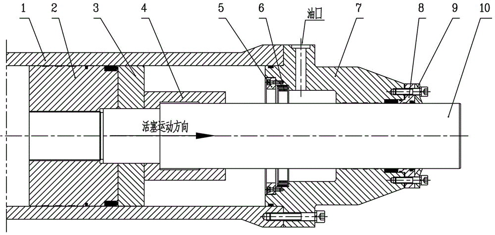
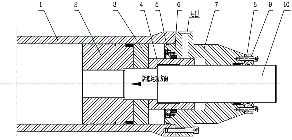
[0028] Such as Figure 1-5 , a hydraulic hoist oil cylinder buffer device, which includes a cylinder body 1, a load-bearing piston 2 is installed in sliding fit inside the cylinder body 1, a piston rod 10 is fixedly installed inside the load-bearing piston 2, and the piston rod 10 One end inside the cylinder body 1 is fixed with a half piston 3 and a buffer sleeve 4, and one end of the cylinder body 1 is equipped with a lower cover 7, and the end of the lower cover 7 located inside the cylinder body 1 is processed with an annular groove. A throttling orifice 6 is installed inside the groove, and the throttling orifice 6 is sealed inside the annular groove through a gland 5. A sealing gland 8 and a scraper ring 9 are installed on the outer end surface of the lower cover 7. The sealing The gland 8 and the scraping ring 9 cooperate with the outer wall of the piston rod 10 .

[0029] Further, the groove width of the inner annular groove of the lower cover 7 is greater than the th...

Embodiment 2

[0035] Such as figure 1 , before the start of buffering, the buffer sleeve 4 moves quickly with the piston rod 10. At this time, the buffer sleeve 4 is located inside the cylinder body 1 without any damping and buffering effect, and the hydraulic oil pushes the piston rod 10 to move quickly, so that the fast gate can fall quickly , to quickly close the water flow; thereby ensuring the purpose of fast closing.

Embodiment 3

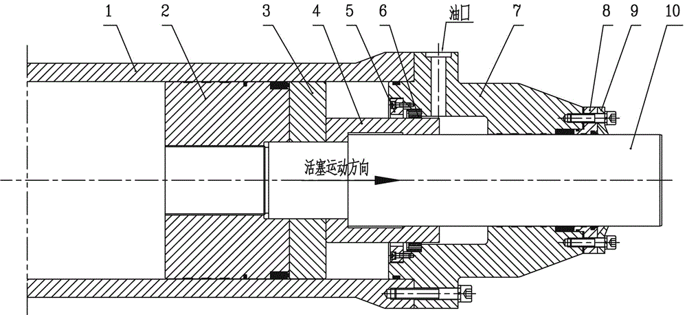
[0037] Such as figure 2 , in the buffer stage, when the fast gate reaches the end of the stroke and is about to reach the bottom sill of the gate, the right end of the buffer sleeve 4 is first inserted into the throttle orifice 6, and the flow cross-sectional area of ​​the hydraulic oil decreases instantly, and the left side of the throttle orifice 6 The pressure of the hydraulic oil increases, pushing the throttle orifice 6 to move to the right, and pressing the throttle orifice 6 tightly on the step of the lower cover 7, so that the 16 annular through holes uniformly distributed on the throttle orifice 6 are in the In the closed state, the hydraulic oil can only flow to the oil tank through the annular gap formed by the outer diameter of the buffer sleeve 4 and the inner diameter of the throttle orifice 6, which plays the role of throttling through the annular gap, so that the speed of the fast door is rapidly reduced, and finally falls smoothly. On the bottom sill of the g...


PUM


Abstract

The invention relates to a hydraulic hoist oil cylinder buffering device and an operation method. The hydraulic hoist oil cylinder buffering device comprises a cylinder body; a bearing piston is installed in the cylinder body in a sliding fit mode, a piston rod is fixedly installed in the bearing piston, and a semi-piston and a buffering sleeve are fixedly installed at the end, located in the cylinder body, of the piston rod; a lower cover is installed at one end of the cylinder body, an annular groove is machined at the end, located in the cylinder body, of the lower cover, and a throttling orifice plate is assembled in the annular groove; the throttling orifice plate is sealed in the annular groove through a pressing cover, and a sealing pressing cover and a dirt scrapping ring are installed on the outer end face of the lower cover and are matched with the outer wall of the piston rod. The hydraulic hoist oil cylinder buffering device is convenient to machine and capable of being easily assembled into a high-speed door hydraulic hoist, so that the buffering effect during door closing is good, hindering on high-pressure oil during door opening is small, the door opening pressure is not increased, and the service lives of sealing parts and a hydraulic system are hardly influenced.

Description

technical field [0001] The invention relates to the field of water conservancy and hydropower, and is used for cushioning when a fast-working gate hydraulic hoist closes the gate, so as to prevent excessive impact caused by excessive speed when the gate reaches the bottom sill. Background technique [0002] In the process of water conservancy construction, such as when building ship locks or building hydroelectric power stations, fast working gates and fast door hydraulic hoists for opening and closing the gates are often used. The function of the fast working gate is that when an emergency occurs, the gate can quickly drop to close the water flow and prevent accidents. Therefore, the closing speed of the fast door hydraulic hoist is fast. If no buffer device is installed in the hydraulic hoist cylinder, when the gate falls to the end of the stroke, it will cause a greater impact on the gate bottom sill and the lower cover of the hoist. At this stage, there are many forms o...

Claims


Application Information

Patent Timeline
Patent Type & Authority Applications(China)
IPC IPC(8): F15B15/22F15B15/14
CPCF15B15/1433F15B15/1457F15B15/22
Inventor 万兴余郭明常征靳晓雷杜浩斌
Owner CSIC ZHONGNAN EQUIP
Why Eureka
Try Eureka