
A fresh air unit control system and control method suitable for radiant air conditioning

A technology for fresh air units and control systems, applied in air conditioning systems, heating and ventilation control systems, and control inputs involving air characteristics, etc. problem, to achieve the effect of improving comfort

Active Publication Date: 2022-05-10
CHONGQING UNIV
View PDF9 Cites 0 Cited by
  • Summary
  • Abstract
  • Description
  • Claims
  • Application Information

AI Technical Summary

Problems solved by technology

However, most of the fresh air fans on the market do not have a ventilation function, and the fresh air still needs to pass through surface coolers and other equipment in transitional seasons. Insufficient energy efficiency ratio used
[0007] (2) At present, most of the fresh air unit products on the market are single fresh air units with a single ventilation mode and lack of active cold or heat sources. However, the indoor design parameters of the radiant ceiling system are special, and the fresh air supply status is unique, requiring fresh air units Cooperating with the radiation system to provide auxiliary heat load treatment can achieve better indoor environmental comfort, but the lack of active cooling or heating sources and the disadvantages of a single ventilation mode limit the performance of fresh air unit products
[0008] (3) At present, some fresh air fans in the market are poorly designed in the self-control part, and the fans cannot adjust the fresh air processing status in time according to indoor and outdoor parameters, making it difficult for the fresh air entering the room to meet the requirements of personnel use, and the comfort is insufficient

Method used


Image

  • A fresh air unit control system and control method suitable for radiant air conditioning
  • A fresh air unit control system and control method suitable for radiant air conditioning
  • A fresh air unit control system and control method suitable for radiant air conditioning

Examples


Embodiment Construction

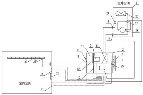
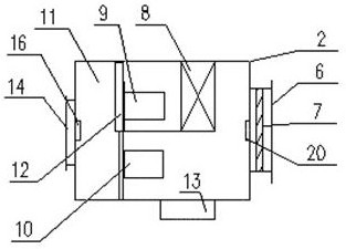
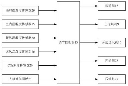
[0041] The invention provides a fresh air unit control system suitable for radiant air conditioning, which is used in conjunction with the radiant air conditioning system of indoor space. The system structure of the fresh air unit control system is as follows figure 1 As shown, it includes the outdoor main unit 1 of the fresh air unit, the indoor unit 2 of the fresh air unit and the control device. Wherein, the outdoor main unit 1 of the fresh air unit includes a compressor 25 and an outdoor heat exchanger 23, and the first refrigerant communication end of the outdoor heat exchanger 23 is connected to the first refrigerant communication port 4 of the outdoor main unit of the fresh air unit through a throttle valve 24, The second refrigerant communication end of the outdoor heat exchanger 23 , the second refrigerant communication port 5 of the outdoor main unit of the fresh air unit, and the suction end and the exhaust end of the compressor 25 are respectively connected through...


PUM


Abstract

The present invention provides a fresh air unit control system and control method suitable for radiant air conditioners. The fresh air unit control system is used in conjunction with the indoor space radiant air conditioner system, and the fresh air dehumidification unit is used to bear the fresh air load, humidity load and indoor part of the sensible heat load. , according to seasonal requirements and changes in the state of outdoor fresh air, the fresh air unit can achieve different functions such as filtration, cooling and dehumidification, auxiliary heating, ventilation, etc. , and strobe through the strobe valve, can freely switch between different working modes, and control the operating mode through the control device, the auxiliary radiation system can adjust the air environment of the indoor space, which can effectively improve the comfort of the indoor environment and the system The energy efficiency ratio of operation solves the problems of insufficient energy efficiency ratio of fresh air transmission in transitional seasons, unreasonable room temperature and humidity, condensation on the surface of radiant panels, and excessive energy consumption.

Description

technical field [0001] The invention belongs to the technical field of indoor ventilation and air conditioning, and in particular relates to a fresh air unit control system and a control method thereof suitable for radiant air conditioning. Background technique [0002] Radiant ceiling cooling technology originated in the 1950s. After decades of research and development, it has gradually been promoted and applied in various regions of the world. Conventional fan coil units realize indoor temperature regulation through air convection, which is difficult to adapt to changes in indoor heat-humidity ratio and has a strong sense of blowing. The ceiling radiant panel mainly provides cooling by means of radiation, the indoor temperature is evenly distributed, there is no temperature dead angle, and there is no air blowing in the room. [0003] In recent years, many scholars at home and abroad have carried out experimental and simulation research on radiant ceiling cooling and inde...

Claims


Application Information

Patent Timeline
Patent Type & Authority Patents(China)
IPC IPC(8): F24F1/0003F24F1/0007F24F1/06F24F11/89F24F11/46F24F11/64F24F11/65F24F11/70F24F13/02
CPCF24F1/0003F24F1/0007F24F1/06F24F11/30F24F11/62F24F11/70F24F13/02F24F2110/00F24F2110/10F24F2110/20F24F2110/50F24F11/65F24F11/64F24F2110/70
Inventor 陈金华宋静姚润明李百战吴璇
Owner CHONGQING UNIV
Learn More