Method for calibrating thermal infrared imager

An infrared thermal imager and application environment technology, applied in the infrared field, can solve the problems of not considering the individual differences of the infrared thermal imager, the response saturation or cutoff, and the poor environmental adaptability, so as to avoid adverse effects and enhance applicability. , the effect of strong adaptability

Active Publication Date: 2017-05-17
简平超
View PDF3 Cites 19 Cited by
  • Summary
  • Abstract
  • Description
  • Claims
  • Application Information

AI Technical Summary

Problems solved by technology

This calibration method is simple and easy to implement, but it has the following shortcomings: First, the adaptability to the environment is not strong
On the one hand, because the infrared thermal imaging camera is a non-contact temperature measurement, it will be affected by the ambient temperature of the atmosphere. The above calibration method is only carried out at a certain ambient temperature. When the ambient temperature changes, the temperature measurement accuracy will be affected.
On the other hand, the response of the infrared detector will change with the ambient temperature. If it is not adjusted in real time, the response will be saturated or cut off. Second, the above calibration method can only be applied to the situation without a germanium window, but When the thermal imager is actually used, in many cases, it is necessary to add a germanium window in front of the lens to protect the optical system and the infrared detector; thirdly, the above calibration method does not consider the individual differences of the thermal imager It must be calibrated separately for each unit, which is not conducive to mass production

Method used


Image

  • Method for calibrating thermal infrared imager
  • Method for calibrating thermal infrared imager
  • Method for calibrating thermal infrared imager

Examples


Embodiment Construction

[0021] The specific implementation manners of the present invention will be further described in detail below in conjunction with the accompanying drawings and embodiments. The following examples are used to illustrate the present invention, but are not intended to limit the scope of the present invention.

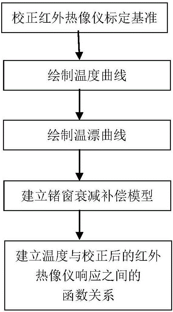
[0022] see figure 1 As shown, a method for calibrating an infrared thermal imager comprises the following steps:

[0023] S1. Correct the detector response sensitivity and focal plane temperature according to the detector measurement range;

[0024] S2, draw temperature curve;

[0025] S3, drawing temperature drift curve;

[0026] S4. Establishing a germanium window attenuation compensation model;

[0027] S5. Fitting the temperature curve and the temperature drift curve, adjusting the response of the thermal imaging camera, and establishing a functional relationship between temperature and the response of the thermal imaging camera after correction based on the german...


PUM


Abstract

The invention provides a method for calibrating a thermal infrared imager. The method, by correcting dynamic range and focal plane temperature of the thermal infrared imager, takes comprehensive considerations of impact factors from temperature drift effects and ge-window attenuating effects, and establishes the function relation between temperatures and the response of the thermal infrared imager after correction so as to calibrate the thermal infrared imager. According to the invention, the method is intended for calibrating the thermal infrared imager, can at the same time calibrate a plurality of thermal infrared imagers, can calibrate accurately and has strong applicability.

Description

technical field [0001] The present invention relates to the field of infrared technology, more specifically, to a method for calibrating an infrared thermal imager. Background technique [0002] The infrared thermal imaging camera uses the infrared detector and the optical imaging objective lens to receive the infrared radiation energy of the measured target, and reflects it on the photosensitive element of the infrared detector to obtain an infrared thermal image. This kind of thermal image corresponds to the thermal distribution field on the surface of the object. Therefore, in addition to imaging, the infrared thermal imager can also measure the temperature by using the different amounts of energy radiated by the object. The temperature measurement of infrared thermal imager is non-contact, and it is widely used in fire protection, electric power, fault diagnosis and other industries. [0003] After the thermal imaging camera is assembled, after non-uniformity correction...

Claims


Application Information

Patent Timeline
Patent Type & Authority Applications(China)
IPC IPC(8): G01J5/00
CPCG01J5/00G01J2005/0077G01J5/80
Inventor 简平超
Owner 简平超
Why Eureka
Try Eureka