Rotor comprehensive testing table and corresponding testing method

A comprehensive test and rotor technology, applied in the field of comprehensive rotor test and rotor comprehensive test bench, can solve the problems of inability to detect the spatial distribution of magnetic steel magnetic field, inability to ensure the stability of motor finished products, inability to test the comprehensive performance of the rotor, etc. Ensure the effect of quality, comprehensive performance and stability

Active Publication Date: 2017-05-17
SUZHOU LVKON NEW ENERGY TECH CO LTD
View PDF9 Cites 4 Cited by
  • Summary
  • Abstract
  • Description
  • Claims
  • Application Information

AI Technical Summary

Problems solved by technology

Existing rotor testing methods can only test the accuracy of the insertion direction of the magnetic steel, but cannot detect the spatial strength distribution of the magnetic steel magnetic field, that is, the existing rotor testing methods cannot test the comprehensive performance of the rotor, making subsequent assembly into the motor. , the finished product stability of the motor cannot be guaranteed

Method used


Image

  • Rotor comprehensive testing table and corresponding testing method
  • Rotor comprehensive testing table and corresponding testing method
  • Rotor comprehensive testing table and corresponding testing method

Examples


Embodiment Construction

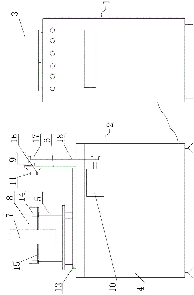
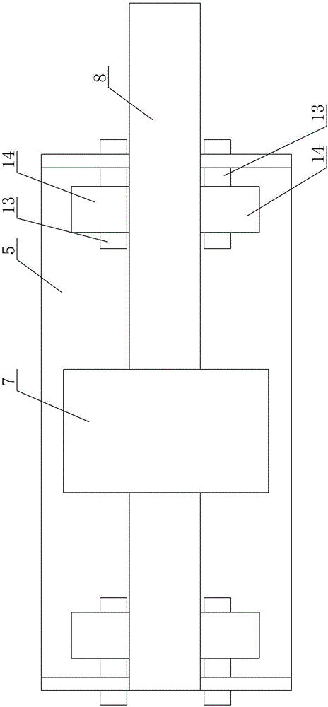
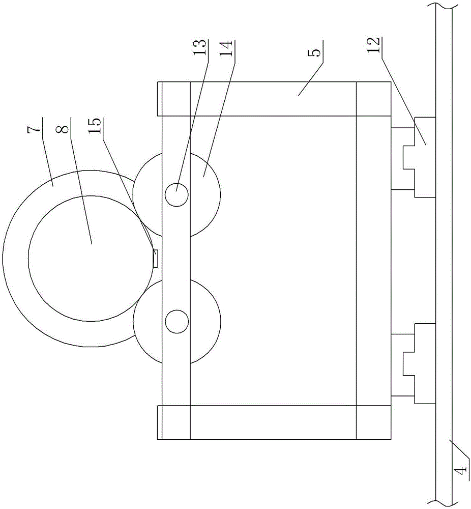
[0020] A rotor comprehensive test bench, see figure 1 : It includes a test control cabinet 1, a test tooling platform 2, a waveform imaging structure 3 is included on the test control cabinet 2, and a space magnetic field scanning device is arranged on the test control cabinet 2 (not shown in the figure, which belongs to the existing mature structure) , the test tooling table 1 includes a frame 4, and the upper end surface of the frame 4 is arranged with a rotor supporting frame 5 and a rotor driving shaft frame 6, and the rotor supporting frame 5 and the rotor driving rotating shaft frame 6 are respectively located on both sides of the upper end surface of the frame 4 Arrangement, the rotor support bracket 5 is used to support the mandrel 8 of the installed rotor 7, the rotor drive shaft frame 6 supports the rotor drive shaft 9, the rotor drive shaft 9 is connected to the output end of the rotating motor 10, and the mandrel 8 can be inserted into the rotor In the positioning ...


PUM


Abstract

The invention provides a rotor comprehensive testing table which performs functions of testing insertion direction accuracy of magnetic steel, effectively monitoring spatial position of the magnetic steel in a rotor and influence of magnetic steel magnetizing amount to the spatial magnetic field of the rotor, ensuring stable comprehensive performance of a rotor which is assembled on a motor, and ensuring high quality of a finished motor. The rotor comprehensive testing table comprises a testing tooling platform and a testing control cabinet. The testing control cabinet comprises a waveform imaging structure. The testing control cabinet is provided with a spatial magnetic field scanning device. The testing tooling platform comprises a frame. The upper end surface of the frame is provided with a rotor support and a rotor driving rotating shaft rack. The rotor support and the rotor driving rotating shaft rack are arranged at two sides of the upper end surface of the frame. The rotor support is used for supporting the mandrel of a mounted rotor. The rotor driving rotating shaft rack supports a rotor driving rotating shaft which is connected with the output end of a rotating motor.

Description

technical field [0001] The invention relates to the technical field of motor rotor testing, in particular to a rotor comprehensive testing platform, and the invention also provides a rotor comprehensive testing method. Background technique [0002] The permanent magnet synchronous motor is a kind of synchronous motor, and its rotor has a strong magnetic magnet (magnetic steel). The performance of the rotor magnetic field directly affects the performance of the motor rotor and thus affects the performance of the motor. Existing rotor testing methods can only test the accuracy of the insertion direction of the magnetic steel, but cannot detect the spatial strength distribution of the magnetic steel magnetic field, that is, the existing rotor testing methods cannot test the comprehensive performance of the rotor, which makes the subsequent assembly to the motor. , the finished product stability of the motor cannot be guaranteed. Contents of the invention [0003] In view of ...

Claims


Application Information

Patent Timeline
Patent Type & Authority Applications(China)
IPC IPC(8): G01R31/34
CPCG01R31/346
Inventor 李磊何省文谢万蛟仲大权
Owner SUZHOU LVKON NEW ENERGY TECH CO LTD
Why Eureka
Try Eureka