Laser active coherence balancing detection polarization analyzer

A technology of balanced detection and polarization analysis, applied in instruments, measurement devices, radio wave measurement systems, etc., can solve problems such as inability to meet measurement requirements, and achieve the effects of wide range of action, strong detection ability, and high signal-to-noise ratio.

Active Publication Date: 2017-05-17
SHANGHAI INST OF OPTICS & FINE MECHANICS CHINESE ACAD OF SCI
4 Cites 6 Cited by

AI-Extracted Technical Summary

Problems solved by technology

These imaging systems all use traditional direct detection methods to detect all Stokes parameters,...

Abstract

A laser active coherence balancing detection polarization analyzer comprises a laser, a vibration spectral module, a polarization generator module, an echo receiving optical antenna, an echo receiving optical antenna, an echo polarization dispersion prism, a horizontal vibration processing module, a vertical vibration processing module and a data processor. The vibration spectral module comprises a first spectroscopic prism, a second optical prism, a first half wave plate and a second half wave plate; the horizontal vibration processing module comprises a first 90 degree 2*4 a pace light bridge connector, a first left channel balance receiver, a first right channel balancing receiver and a first complexizer. The vertical vibration processing module comprises a second 90 degree 2*4 a pace light bridge connector, a second left channel balance receiver, a second right channel balancing receiver and a second complexizer. The laser active coherence balancing detection polarization analyzer has the advantages of high receiving sensitivity, high detection ability, high signal-to-noise ratio and wide operating range. The laser active coherence balancing detection polarization analyzer is an important technology improvement to obtain the target polarization information by active lighting.

Application Domain

Technology Topic

Image

  • Laser active coherence balancing detection polarization analyzer
  • Laser active coherence balancing detection polarization analyzer
  • Laser active coherence balancing detection polarization analyzer

Examples

  • Experimental program(1)

Example Embodiment

[0024] The present invention will be described in further detail below with reference to the accompanying drawings and embodiments, but the protection scope of the present invention should not be limited by this.
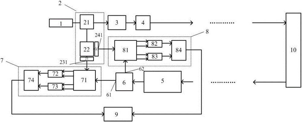
[0025] see first figure 1 , figure 1 This is the structural principle block diagram of the laser active coherent balance detection polarization analyzer of the present invention. It can be seen from the figure that the present invention is a laser active coherent balance detection polarization analyzer based on a 90° 2×4 spatial optical bridge, which consists of a laser 1, a local oscillator optical splitting module 2, a polarization state generating module 3, an optical transmitting antenna 4, The echo receiving optical antenna 5 , the echo polarization beam splitting prism 6 , the horizontal vibration processing module 7 , the vertical vibration processing module 8 and the data processor 9 .
[0026] The main optical axis of the laser output of the laser 1 is the local oscillator optical splitting module 2 , the polarization state generating module 3 , and the optical transmitting antenna 4 in sequence. The laser light emitted by the laser 1 is split by the first beam splitting prism 21 of the local oscillator light splitting module 2, and a part of the emitted beam enters the polarization state generating module 3, and is irradiated to the surface of the target 10 through the optical transmitting antenna 4; the other part passes through the second beam splitting. Prism 22, and by adjusting the optical axis angle of the first half-wave plate 23, a local oscillator laser beam in the horizontal vibration direction is formed at its first outgoing end 231, and at the same time by adjusting the optical axis angle of the second half-wave plate 24, at the second outgoing end 231 The end 241 forms a local oscillator laser beam perpendicular to the vibration direction. After the emission beam irradiated on the surface of the target 10 is reflected, the echo beam carrying the target polarization information enters the echo receiving optical antenna 5, and is split by the echo polarization beam splitting prism 6, and formed at the first exit end 61. The target echo beam in the horizontal vibration direction and the second outgoing end 62 form the target echo beam in the vertical vibration direction.
[0027] The local oscillator laser beam and the target echo beam in the horizontal vibration direction are input to the horizontal vibration processing module 7, and pass through the first 90° 2×4 spatial optical bridge 71 to generate four beam outputs with a phase difference of 90° in sequence. , in which the two beams with a phase shift of 180° are photoelectrically detected by the left channel balanced receiver 72 to become a real number signal, which is further converted into a left channel digital signal; the other two beams with a phase shift of 180° are detected by the right channel balanced receiver 73 . The photodetection becomes a real signal, which is further converted into a right channel digital signal. The left channel digital signal and the right channel digital signal are combined by a complex digitizer 74 and converted into a complex signal of the light level component of the echo signal.
[0028]The local oscillator laser beam and the target echo beam in the vertical vibration direction are input to the vertical vibration processing module 8, and pass through the second 90° 2×4 spatial optical bridge 81 to generate four beam outputs with a phase difference of 90° in turn. , in which the two beams with a phase shift of 180° are photoelectrically detected by the left channel balanced receiver 82 and converted into a real number signal, which is further converted into a left channel digital signal; the other two beams with a phase shift of 180° are detected by the right channel balanced receiver 83 . The photodetection becomes a real signal, which is further converted into a right channel digital signal. The left channel digital signal and the right channel digital signal are combined by a complex digitizer 84 and converted into a complex signal of the vertical component of the echo signal light.
[0029] The complex signal of the horizontal component and the vertical component of the echo signal light is expressed by the data processor 9 as the Stokes vector of the echo light field. By adjusting the polarization state generation module 3 to change the polarization state of the emitted light beam, the Stokes vectors of multiple groups of emitted light beams and the echo light field are obtained, and on this basis, the Mueller matrix carrying the target polarization information is obtained by calculation, and finally the target to be measured is obtained. polarization properties.
[0030] The polarization state generating module 3 has two different types of devices. The first is composed of a linear polarizer and a quarter-wave plate. By adjusting the angle of the linear polarizer and the angle between the fast axis of the quarter-wave plate, the outgoing laser light has different polarization states. The second is composed of a polarizer and a phase modulator, and the required laser light of different polarization states is generated by adjusting the voltage acting on the phase delay modulator.
[0031] The transmitting antenna module 4 has a focal length of F 1 The lens is composed of , and the beam waist radius of the laser output can be determined by Calculated. λ is the working wavelength of laser 1, ω 0 is the beam waist radius of laser 1.
[0032] The echo receiving optical antenna 5 includes a focal length of f 1 The first lens 51, the aperture stop 52 and the focal length f 2 the second lens 53. The first lens 51 and the second lens 53 are confocal, and the aperture diaphragm 52 is located at the confocal point for filtering, and the beam reduction ratio is M=f 1 /f 2 Calculated.
[0033] The following uses a target point to explain the imaging principle of the laser active coherent balance detection polarization analyzer of the present invention:
[0034] The detection distance from the system to the target is z, and the coordinate system of the target surface is set to (x k ,y k ), the emission light source selects a polarization-maintaining single-mode laser with a wavelength of λ and a power of P, and its beam waist radius is ω 0. Launching telescope focal length F 1 ,, and its laser beam waist radius can be calculated by: The illumination light field on the target surface is expressed as:
[0035]
[0036] in,
[0037]
[0038]
[0039] The diameter of the illumination spot on the target surface is expressed as: The echo Fresnel diffraction light field that propagates to the receiving telescope system after being reflected by the target is expressed as:
[0040]
[0041] where ρ(x k ,y k ,z)exp[jφ ρ (x k ,y k ,z)] is the reflectivity of the target.
[0042] The transmission distance of the local oscillator beam is z 0 , then the relative time delay of the target is Let f be the echo signal frequency, is the initial phase of the emitted laser, is the phase delay of the target channel, As the phase delay of the local oscillator channel, the echo signal is expressed as:
[0043]
[0044] The local oscillator signal is expressed as:
[0045] For the LO laser beam and target echo beam in the horizontal vibration direction:
[0046]
[0047]
[0048] Therefore, the output of the left-balanced receiver is:
[0049]
[0050] The output of the right balanced receiver is:
[0051]
[0052] Among them, A i represents a constant related to signal strength and detector, represents the initial phase shift. After pluralization,
[0053]
[0054] For the LO laser beam and the target echo beam in the vertical vibration direction:
[0055]
[0056]
[0057] Therefore, the output of the left-balanced receiver is:
[0058]
[0059] The output of the right balanced receiver is:
[0060]
[0061] After pluralization,
[0062]
[0063] Assuming that the amplitude of the local oscillator signal is 1 and the initial phase shift from the signal light is 0, the above-mentioned complex signal containing echo information is simplified to the expression form of the echo light field, and its polarization state can be expressed as:
[0064]
[0065]
[0066] E x ,δ x represent the vibration component and vibration phase along the horizontal direction (x direction), respectively, E y ,δ y Respectively represent the vibration component and phase along the vertical direction (y direction), δ=δ y -δ x represents the phase difference of the two components. Therefore, the Stokes vector of the echo light field can be obtained by the definition formula:
[0067]
[0068]
[0069] S' 2 =2E 0x E 0y cosδ
[0070] S' 3 =2E 0x E 0y sinδ
[0071] Stokes vector of the echo light field The Stokes vector of the outgoing laser beam can be The linear combination of :
[0072]
[0073] The Mueller matrix is ​​expressed as:
[0074] .

PUM

no PUM

Description & Claims & Application Information

We can also present the details of the Description, Claims and Application information to help users get a comprehensive understanding of the technical details of the patent, such as background art, summary of invention, brief description of drawings, description of embodiments, and other original content. On the other hand, users can also determine the specific scope of protection of the technology through the list of claims; as well as understand the changes in the life cycle of the technology with the presentation of the patent timeline. Login to view more.

Similar technology patents

Ultrasound diagnosis apparatus

Owner:FUJIFILM HEALTHCARE CORP

Classification and recommendation of technical efficacy words

  • Strong detection ability
  • Improve receiver sensitivity

Botnet host detection method

ActiveCN109391602ASolving Extraction and Selection DifficultiesStrong detection abilityComputing modelsTransmissionBotnetLegal domain
Owner:北京金睛云华科技有限公司

Broadband signal orientation estimation method based on conditional wave number spectral density

ActiveCN111175727AHigh main-to-sidelobe ratioStrong detection abilityWave based measurement systemsBroadbandingLinear array
Owner:INST OF ACOUSTICS CHINESE ACAD OF SCI

Portable underground pipeline detection device

InactiveCN109490984AStrong detection abilityEasy to useGeological measurementsUnderground pipelineEngineering
Owner:NORTH CHINA UNIV OF WATER RESOURCES & ELECTRIC POWER

Communication time slot allocation method and device, and server

ActiveCN111586566AReduce radar signal interferenceStrong detection abilityParticular environment based servicesLocation information based serviceRadar signalsReal-time computing
Owner:GUANGZHOU CHENGXING ZHIDONG AUTOMOTIVE TECH CO LTD +1

Pipeline detection robot

ActiveCN108626516ASmall sizeStrong detection abilityPigs/molesMiddle segmentUltrasonic sensor
Owner:XIANGTAN HONGYUAN ELECTRONICS SCI & TECH CO LTD
Why Eureka
Try Eureka