

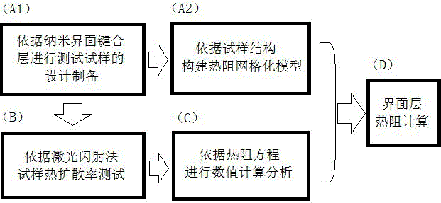
Microelectronic device nanometer interface bonding layer thermal resistance analyzing method
A technology of microelectronic devices and analysis methods, which is applied in the fields of instruments, electrical digital data processing, and special data processing applications, etc., can solve problems such as the inability to test the thermal resistance of the bonding layer at the nanometer interface, achieve improved bonding quality, and achieve accurate characterization , Improve the effect of heat dissipation
- Summary
- Abstract
- Description
- Claims
- Application Information
AI Technical Summary
Problems solved by technology
Method used
Image

Examples
Embodiment
[0023] Thermal resistance analysis of benzocyclobutene (BCB) interfacial layer for wafer-level silicon-silicon bonding in microelectronic MEMS devices:
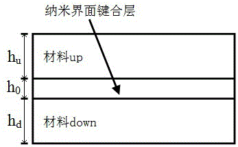
[0024] ①According to the actual size of the MEMS device wafer-level silicon-silicon bonded benzocyclobutene interface layer, design a three-layer test structure: Si-BCB-Si, the thickness of the upper silicon layer and the thickness of the lower silicon layer are equal to h u = h d =0.48mm, the thickness of the BCB nano bonding layer is 100nm; the test sample is prepared according to the design, and its plane size is Φ=12.7±0.05mm;
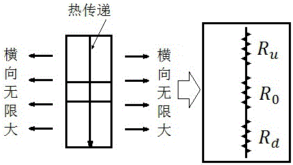
[0025] According to the design of Si-BCB-Si, the grid of the thermal resistance during the flash method test is carried out, that is, the heat in the heat transfer process first passes through the thermal resistance , and then through the thermal resistance , and finally through the thermal resistance , is a three-layer thermal resistance series structure, and the total thermal resistance ...
PUM
| Property | Measurement | Unit |
|---|---|---|
| thickness | aaaaa | aaaaa |
| thickness | aaaaa | aaaaa |
| diameter | aaaaa | aaaaa |
Abstract
Description
Claims
Application Information