Onboard electronic part device for rail transit

A technology for rail transit and electrical devices, applied in circuit thermal devices, printed circuit components, etc., can solve problems such as reducing overall reliability, increasing overall complexity, and increasing chassis failure points, achieving compact structure and excellent heat dissipation effect. , the effect of reducing train risk

Inactive Publication Date: 2017-05-17
ZHUZHOU CSR TIMES ELECTRIC CO LTD
View PDF5 Cites 1 Cited by
  • Summary
  • Abstract
  • Description
  • Claims
  • Application Information

AI Technical Summary

Problems solved by technology

[0003] (1) Adding a ventilation fan in the chassis can strengthen the air circulation in the chassis to achieve the purpose of heat dissipation, but adding a ventilation fan requires correspondingly increasing the fan control and power supply, which will increase the possible failure points of the chassis and reduce the overall reliability. And it will inevitably increase the volume of the chassis, which is difficult to achieve in the limited space on the car.
[0004] (2) Adding a profile radiator to a single device can achieve the purpose of heat dissipation for a single device by increasing the heat dissipation area, but this will increase the overall temperature in the chassis, and the heat dissipation effect is not obvious when the ambient temperature is high, and When the installation board is relatively compact, space constraints make it impossible to install this type of radiator.
[0005] (3) The water-cooling system will also increase the overall complexity, greatly increase the cost, and make assembly and maintenance difficult.
[0006] (4) A fan is installed outside the chassis, and the cooling effect of forced air cooling is good, but the extra cost increases, the limitation of external conditions such as control power supply and installation space, and the need for noise control on the car make this type of solution rarely used

Method used


Image

  • Onboard electronic part device for rail transit
  • Onboard electronic part device for rail transit
  • Onboard electronic part device for rail transit

Examples


Embodiment Construction

[0032] The present invention will be described in further detail below in conjunction with specific embodiments and accompanying drawings.

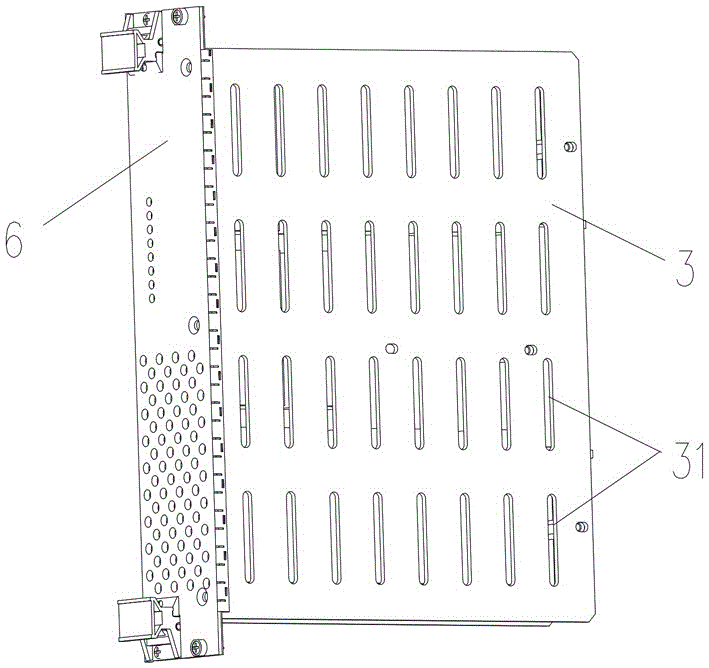
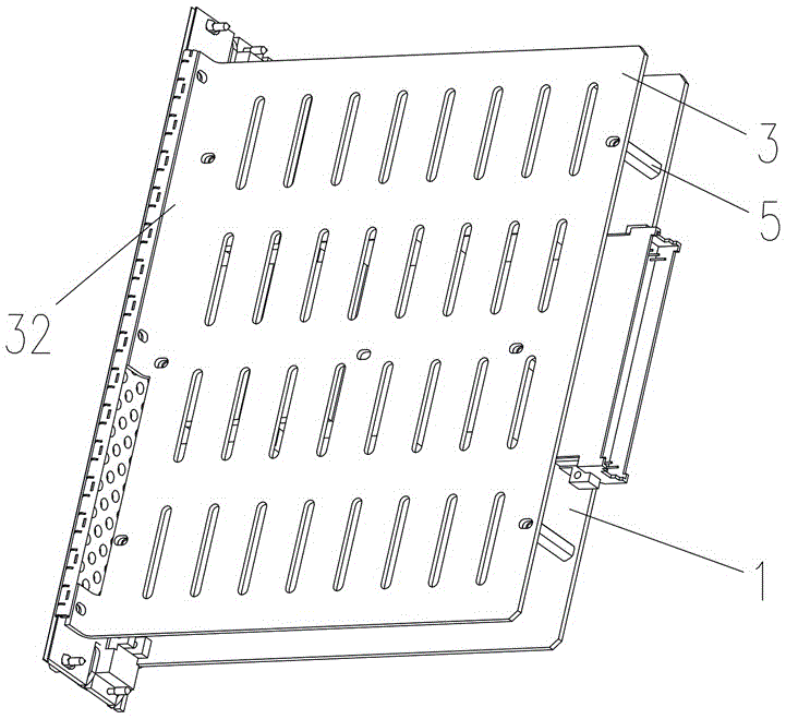
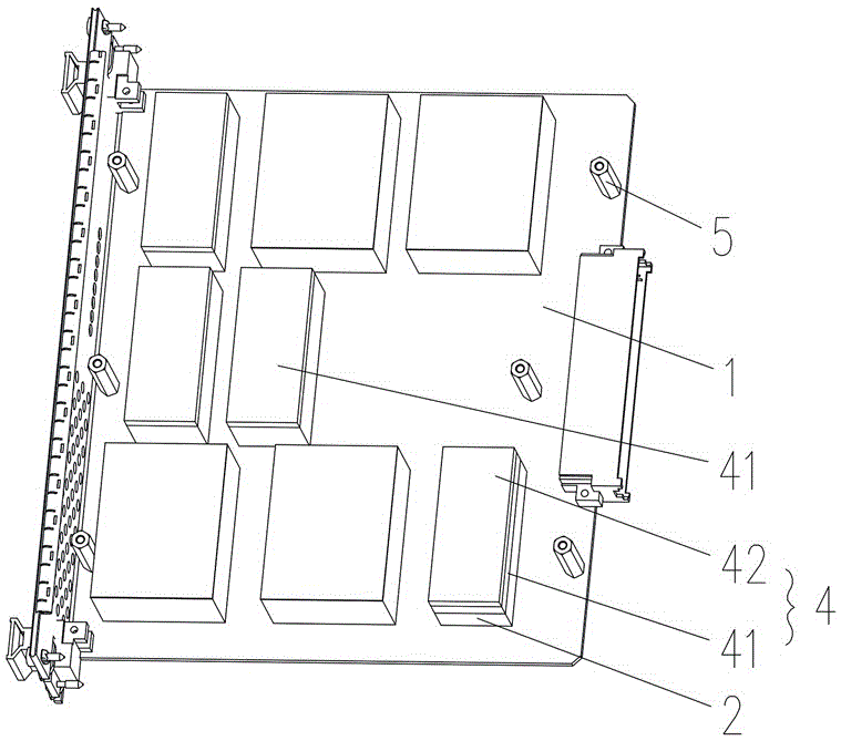
[0033] like Figure 1 to Figure 5 As shown, the present invention provides a board-mounted electrical device device for rail transit, including a printed circuit board 1, on which a plurality of electronic devices 2 with different heights are installed, and a matching The heat dissipation plate 3 and a plurality of heat conduction pad assemblies 4 with different thicknesses, and a plurality of electronic devices 2 are arranged and fixed between the printed circuit board 1 and the heat dissipation plate 3, and the plurality of heat conduction pad assemblies 4 with different thicknesses are correspondingly filled in the The gap between the electronic devices 2 with different heights and the heat sink 3 is used for adjustment so that each electronic device 2 is tightly pressed against the heat sink 3 and then conducts heat to the heat sink 3...


PUM


Abstract

The invention discloses an onboard electronic part device for rail transit. The onboard electronic part device comprises a printed circuit board, and multiple electronic parts different in height are mounted on the printed circuit board; the onboard electronic part device comprises a heat radiation board and multiple heat conduction pad components different in height, the heat radiation board and the heat conduction pad components are matched with each other, the electronic parts are pressed between the printed circuit board and the heat radiation board, and the heat conduction pad components are correspondingly filled between the electronic parts and the heat radiation board and used for adjusting to enable each electronic part to be compressed and fitted with the heat radiation board to conduct heat onto the heat radiation board for heat radiation. The onboard electronic part device has the advantages of scientific and reasonable design, simple and compact structure and good heat radiation effect.

Description

technical field [0001] The invention mainly relates to the field of rail transportation equipment, in particular to a board-mounted electrical device device for rail transportation. Background technique [0002] In the power distribution cabinet on the EMU, the electronic devices (such as relays) used are often integrated into different printed circuit boards according to their functions, and then each single board is assembled into the chassis. Frequent actions of electronic devices (such as relays) or coils that are energized for a long time will continue to generate heat, forming a heat source and generating high temperatures. Because the space in the chassis is not well ventilated, the heat is not easy to dissipate. Long-term high temperatures will lead to performance degradation or even loss of function of the relay. , leading to serious consequences. Therefore, it is necessary to design a heat dissipation scheme to achieve heat dissipation and cooling of half-loaded d...

Claims


Application Information

Patent Timeline
Patent Type & Authority Applications(China)
IPC IPC(8): H05K1/02
CPCH05K1/0203
Inventor 王伟杨亚斌陈雨雨代少飞梁彦锋郑中尧
Owner ZHUZHOU CSR TIMES ELECTRIC CO LTD
Why Eureka
Try Eureka