Fine particle polymerizer and high-efficiency dedusting defogging integrated system

A technology of fine particles and aggregators, applied in the field of flue gas purification, can solve problems such as inability to judge technical links, inability to diagnose and eliminate defects, and inability to achieve the effect of collaborative governance.

Pending Publication Date: 2017-05-24
DEMISTER SHANGHAI ENVIRONMENTAL TECH
View PDF8 Cites 9 Cited by
  • Summary
  • Abstract
  • Description
  • Claims
  • Application Information

AI Technical Summary

Problems solved by technology

[0016] 3. Adopt the "coordinated governance plan", once the outlet concentration of smoke and dust is greater than 5mg / Nm 3 , it is impossible to judge which technical link fails to achieve the effect of collaborative governance, so it is also impossible to diagnose how to eliminate defects in the system

Method used


Image

  • Fine particle polymerizer and high-efficiency dedusting defogging integrated system
  • Fine particle polymerizer and high-efficiency dedusting defogging integrated system
  • Fine particle polymerizer and high-efficiency dedusting defogging integrated system

Examples


Embodiment 1

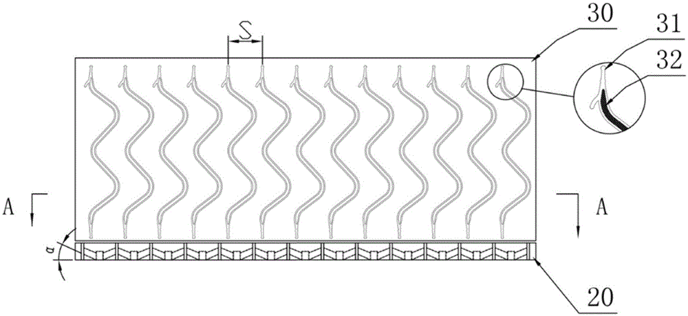
[0116] As attached figure 1 As shown, the first solution of the integrated high-efficiency dust removal and mist removal system of this embodiment is that the integrated dust removal and mist removal system is installed in the absorption tower. The system includes two parts: a fine particle polymerizer 20 and a condensation wet film centrifugal separator 30. The fine particle polymerizer 20 and the condensed wet film centrifugal separator 30 are arranged on the cross section of the flue gas flow containing fine particles. The plane where the fine particle aggregator 20 is located and the plane where the condensation wet film centrifugal separator 30 is located are substantially perpendicular to the direction of the flue gas flow.

[0117] The fine particle polymerizer 20 and the condensed wet film centrifugal separator 30 are installed on a layer of support beams.

[0118] The lower part of the fine particle polymerizer 20 and the upper part of the condensed wet film centrifugal se...

Embodiment 2

[0139] Such as Picture 9 As shown, the integrated dust removal and mist removal system of this embodiment includes a first-stage pre-processor 10, a fine particle polymerizer 20, a condensed wet film centrifugal separator 30 (or corrugated plate gas-liquid separator), and an ultra-fine separator 40. And all are installed in the absorption tower.

[0140] After the boiler tail gas passes through the electrostatic precipitator, the smoke and dust concentration is ≤20mg / Nm 3 Enter the desulfurization absorption tower 60. In the absorption tower 60, there are 3-6 layers of spraying layers 70 and possibly 1 or 2 layers of trays or FGD Plus 80. The flue gas passes through the trays or FGD Plus 80 and spraying layer 70 and then undergoes pretreatment in sequence Reactor 10, fine particle polymerizer 20, condensed wet film centrifugal separator 30, and ultrafine separator 40. Picture 9 The arrow in indicates the flow direction of the smoke.

[0141] The pre-separator 10 includes a prima...


PUM

PropertyMeasurementUnit
angleaaaaaaaaaa
thicknessaaaaaaaaaa
particle diameteraaaaaaaaaa

Abstract

The invention discloses a polymerizer for polymerization of fine particles; the polymerizer includes one or more cyclone devices, and each cyclone device comprises at least two rotational flow vanes; the rotational flow vanes are set to make a gas flow containing fine particles to form a rotary gas flow by the cyclone devices. The invention also provides a dedusting defogging integrated system comprising the polymerizer and an integrated dedusting defogging method. The high-efficiency dedusting defogging integrated system can effectively remove most of PM2.5 fine dust in the gas flow, and has quite high practical application value on governance of the fine particles in flue gas; moreover, the system is low device investment cost, low in energy consumption, and long-term running reliability, and can be used in the fields of flue gas purification of thermal power plants, steel plants, paper-making factories, glass factories, chemical plants and production workshops with particle emissions and the like.

Description

Technical field [0001] The invention relates to the field of flue gas purification, in particular to a fine particle polymerizer and an integrated system for dust removal and mist removal used in tail gas treatment systems such as thermal power plants, steel plants, paper mills, glass plants, chemical plants and the like. Background technique [0002] In order to achieve ultra-clean emissions or even near zero emissions from coal-fired thermal power plants, the state proposed the "50355" indicator, which requires coal-fired power plants to emit less than 5mg / Nm of smoke and dust respectively. 3 (Meet the standard of gas-fired unit), sulfur dioxide SO 2 The emission standard is less than 35mg / Nm 3 , Nitrogen oxide NO X Concentration is less than 50mg / Nm 3 . [0003] In order to achieve ultra-clean emission or even near-zero emission standards for the concentration of smoke and dust, the wet electrostatic precipitator has large investment, high operating energy consumption, large volu...

Claims


Application Information

Patent Timeline
Patent Type & Authority Applications(China)
IPC IPC(8): B01D51/02B01D45/16B01D50/00
Inventor 程子剑张红彬张爱丰龚磊
Owner DEMISTER SHANGHAI ENVIRONMENTAL TECH
Why Eureka
Try Eureka