Glue outlet control method of gluing machine and glue outlet control device

A control method and a technology of a control device, which are applied to the device and coating of the surface coating liquid, can solve the problems that plague construction enterprises, such as huge size, waste of colloid, etc., and achieve the prevention of pollution of the working environment, accurate and clean glue control, The effect of preventing colloid waste

Inactive Publication Date: 2017-05-24
东方诚建设集团有限公司
View PDF10 Cites 2 Cited by
  • Summary
  • Abstract
  • Description
  • Claims
  • Application Information

AI Technical Summary

Problems solved by technology

However, the structure of the existing gluing machine is complex and huge, requiring on-site water supply and oil supply support, and the complex gluing machine system is difficult to transport and install, which has become a long-term technical problem for construction companies
In particular, after the colloid in the plastic bag of the existing glue applicator system is used up, the pressure system needs to be disassembled, and the pressure system must be recalibrated after replacing the loading and unloading plastic bag. Glue is a waste of colloid, and manual monitoring is required during operation. When the plastic bag is used up or the pressure is insufficient, the gluing operation cannot be stopped in time, which often results in uneven gluing. Pollution to the working environment

Method used


Image

  • Glue outlet control method of gluing machine and glue outlet control device
  • Glue outlet control method of gluing machine and glue outlet control device
  • Glue outlet control method of gluing machine and glue outlet control device

Examples


Embodiment Construction

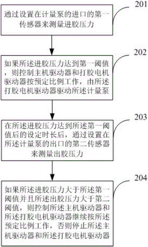
[0032] figure 2 It is a flow chart of the steps of the method embodiment of the present invention, such as figure 2 As shown, the embodiment of the present invention provides a method for controlling glue output of a glue applicator, including:

[0033] Step 201, measure the glue feeding pressure through the first sensor arranged at the inlet of the metering pump;

[0034] Step 202, if the glue feeding pressure reaches the first threshold, control the driver of the main engine and the glue-making motor driver to work in a predetermined ratio, and the glue-making motor driver drives the metering pump;

[0035] Step 203, measuring the glue discharge pressure through a second sensor arranged at the outlet of the metering pump after the glue feed pressure reaches the first threshold for a set period of time;

[0036] Step 204, if the glue-feeding pressure is greater than the first threshold and the glue-discharging pressure is greater than the second threshold, then control th...


PUM


Abstract

The invention provides a glue outlet control method of a gluing machine and a glue outlet control device, accurate and clean glue outlet control is provided for field gluing operation, the gluing quality is improved and the glue waste and the environmental pollution are prevented. The glue outlet control method of the gluing machine comprises the following steps that a first sensor arranged in an inlet of a metering pump is used for measuring the glue inlet pressure; if the glue inlet pressure reaches a first threshold, a host machine drive and a gluing motor drive are controlled to work according to a preset ratio, and the gluing motor drive drives the metering pump; after the glue inlet pressure reaches the first threshold for a set time length, a second sensor arranged in an outlet of the metering pump is used for measuring the glue outlet pressure; if the glue inlet pressure is higher than the first threshold, and the glue outlet pressure is higher than the second threshold, the host machine drive and the gluing motor drive are controlled to continuously work according to the preset ratio; and otherwise, the host machine drive and the gluing motor drive are stopped.

Description

technical field [0001] The invention relates to the field of building steel structures, in particular to a glue discharge control method and a glue discharge control device of a glue applicator. Background technique [0002] At present, many factories adopt the form of steel structure. The characteristics of steel structure factory buildings are as follows: 1. Steel structure buildings are light in weight, high in strength and large in span; 2. The construction period of steel structure buildings is short, which reduces investment costs accordingly; 3. Fire resistance of steel structure buildings High, strong corrosion resistance; 4. The steel structure building is easy to move, and the recycling is pollution-free. [0003] figure 1 It is a schematic diagram of a steel structure factory building, such as figure 1 As shown, the top of the factory building is a metal roof panel 11 extending obliquely to the left and right sides with a certain slope, the left and right sides ...

Claims


Application Information

Patent Timeline
Patent Type & Authority Applications(China)
IPC IPC(8): B05C11/10B05C13/02
CPCB05C11/1005B05C13/02
Inventor 多跃刚陈胜明王越
Owner 东方诚建设集团有限公司
Why Eureka
Try Eureka