Eureka AIR delivers breakthrough ideas for toughest innovation challenges, trusted by R&D personnel around the world.

Cutting mechanism

A technology of fixing plates and connecting rods, applied in shearing devices, metal processing equipment, manufacturing tools, etc., can solve problems such as affecting the overall quality of the finished product, easy deformation of the incision, and difficulty in direct cutting of long cylindrical raw materials. Standard cutting surface, saving labor cost

Active Publication Date: 2017-05-24
徐州天骋智能科技有限公司
View PDF7 Cites 1 Cited by
  • Summary
  • Abstract
  • Description
  • Claims
  • Application Information

AI Technical Summary

Problems solved by technology

[0003] The invention provides a material cutting mechanism, which solves the problems in the prior art that it is difficult to directly cut long cylindrical raw materials with slits, the incision is easily deformed, and the overall quality of the finished product is affected.

Method used


Image

  • Cutting mechanism
  • Cutting mechanism
  • Cutting mechanism

Examples


Embodiment Construction

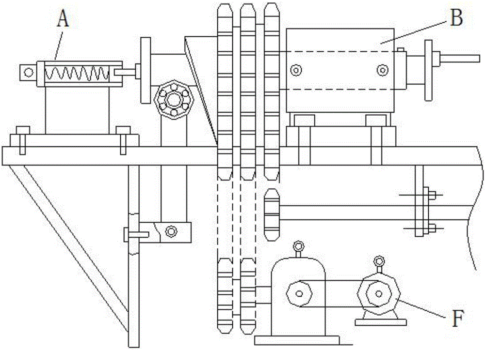
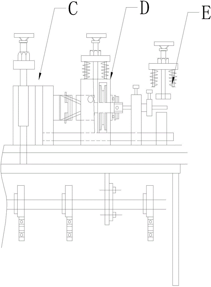
[0013] refer to figure 1 , figure 2 , the overall structure of the elastic cylindrical pin processing device where the present invention is located is that, according to the feeding route, a stretching head pressure support A, a stretching head mechanism B, a compression mechanism C, a material cutting mechanism D, a discharge Mechanism E, wherein the stretching head mechanism B, the pressing mechanism C, the cutting mechanism D, and the unloading mechanism E are respectively connected to the power mechanism F through their own transmission parts.

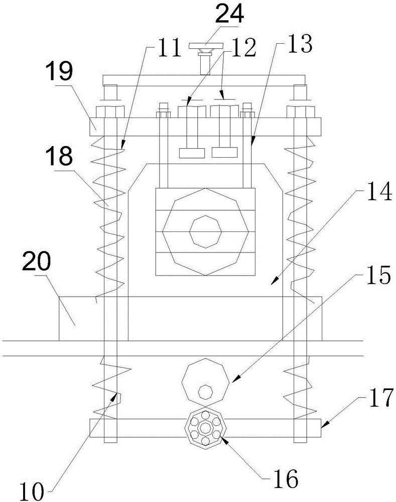
[0014] refer to image 3 , Figure 4 , the structure of the material cutting mechanism D is that a middle fixed plate 20 is fixedly installed on the upper surface of the workbench, a box body 14 is installed on the upper surface of the middle fixed plate 20, and a knife is installed in the horizontal direction of the box body 14 through two groups of bearings-6. The shaft 9 and the cutter shaft 9 are equipped with a planar bear...


PUM


Abstract

The invention discloses a cutting mechanism. The cutting mechanism comprises a box body mounted on the upper surface of a middle fixed plate; a cutter shaft is horizontally mounted in the box body; a plane bearing 1 is mounted at one end, towards a feed port, of the cutter shaft; the outer periphery of the plane bearing 1 is sleeved with a movable sleeve; guide columns and cutter frames are arranged on the outer end surface of the plane bearing 1; a plane bearing 2 and a combination cap are mounted at one end, toward a discharge port, of the cutter shaft; the outer periphery of the middle part of the cutter shaft is fixedly sleeved with a belt wheel; two connecting rods are inserted in the middle fixed plate; an upper fixed plate is fixedly mounted at the upper ends of the two connecting rods; a limiting screw rod is downwards mounted on the center line of the upper fixed plate; taper cutter feeding rods are respectively hung on two edges of the upper fixed plate; the two taper cutter feeding rods are downwards connected with two guide columns; each guide column is in transmission connection with one corresponding cutter frame; a bearing bracket is mounted at the lower ends of the two connecting rods; and a bearing 2 in the bearing bracket is in rolling contact with the outer peripheral surface of a cam. The device is standard in cutting surface and stable in product quality.

Description

technical field [0001] The invention belongs to the technical field of mechanical equipment, is used for processing elastic straight pins, and relates to a material cutting mechanism. Background technique [0002] The existing elastic cylindrical pin products are widely used, and in various locks and stainless steel furniture connectors, the amount used reaches one tenth of that of screws and nuts. However, in the production of elastic cylindrical pins in the past, it is difficult to cut the long cylindrical raw material with slits directly, and the incision is easily deformed, which makes the cutting surface of the product non-standard and affects the overall processing quality. Contents of the invention [0003] The invention provides a material cutting mechanism, which solves the problems in the prior art that it is difficult to directly cut long cylindrical raw materials with slits, the incision is easily deformed, and the overall quality of the finished product is aff...

Claims


Application Information

Patent Timeline
IPC IPC(8): B23D19/04B23D33/02
CPCB23D19/04B23D33/02
Inventor 李军计
Owner 徐州天骋智能科技有限公司
Why Eureka
Eureka Blog
Learn More