Automotive shock absorber set correction device

A technology of automobile shock absorption and correction device, which is applied in the direction of workpiece clamping device and manufacturing tools, which can solve the problems of heavy workload of operators, poor sealing of shock absorber, shortening of spring stroke, etc., and achieve the effect of improving safety

Active Publication Date: 2018-12-28
UNIV FOR SCI & TECH ZHENGZHOU
View PDF7 Cites 0 Cited by
  • Summary
  • Abstract
  • Description
  • Claims
  • Application Information

AI Technical Summary

Problems solved by technology

Driving on roads with poor road conditions for a long time or due to bad driving habits (frequently stepping on the brakes and slamming on the accelerator) will cause irreversible deformation of the spring and shorten the spring stroke, which not only affects the comfort of the vehicle, but also lasts for a long time. Use will cause wear and tear between the spring and the shock absorber and cause abnormal noise. At this time, it is necessary to correct the spring to prevent oil leakage from poor sealing of the shock absorber. However, there are the following technical problems when correcting the spring: due to There are differences in the model of the suit, such as the difference in the diameter of the spring, the difference in the diameter of the two ends of the same spring, the difference in the material, outer diameter and surface treatment of the spring steel, and the multiple parts of the shock absorber. For example, the size of the sleeve and the piston, the structure of the spring pressing plate 30 and the carrier 26 are different (such as figure 1 ball bearing and U-head bearing shown)
The disadvantage of this structure: the device is only used for fixing the shock absorber or the shock absorber, and is not suitable for the installation of the spring and the shock absorber, and the shock absorber is manually pushed into the two jaws during use In the process of advancing, due to the strong elastic force of the self-returning spring, the operator at this station has a relatively large workload

Method used


Image

  • Automotive shock absorber set correction device
  • Automotive shock absorber set correction device
  • Automotive shock absorber set correction device

Examples


Embodiment 1

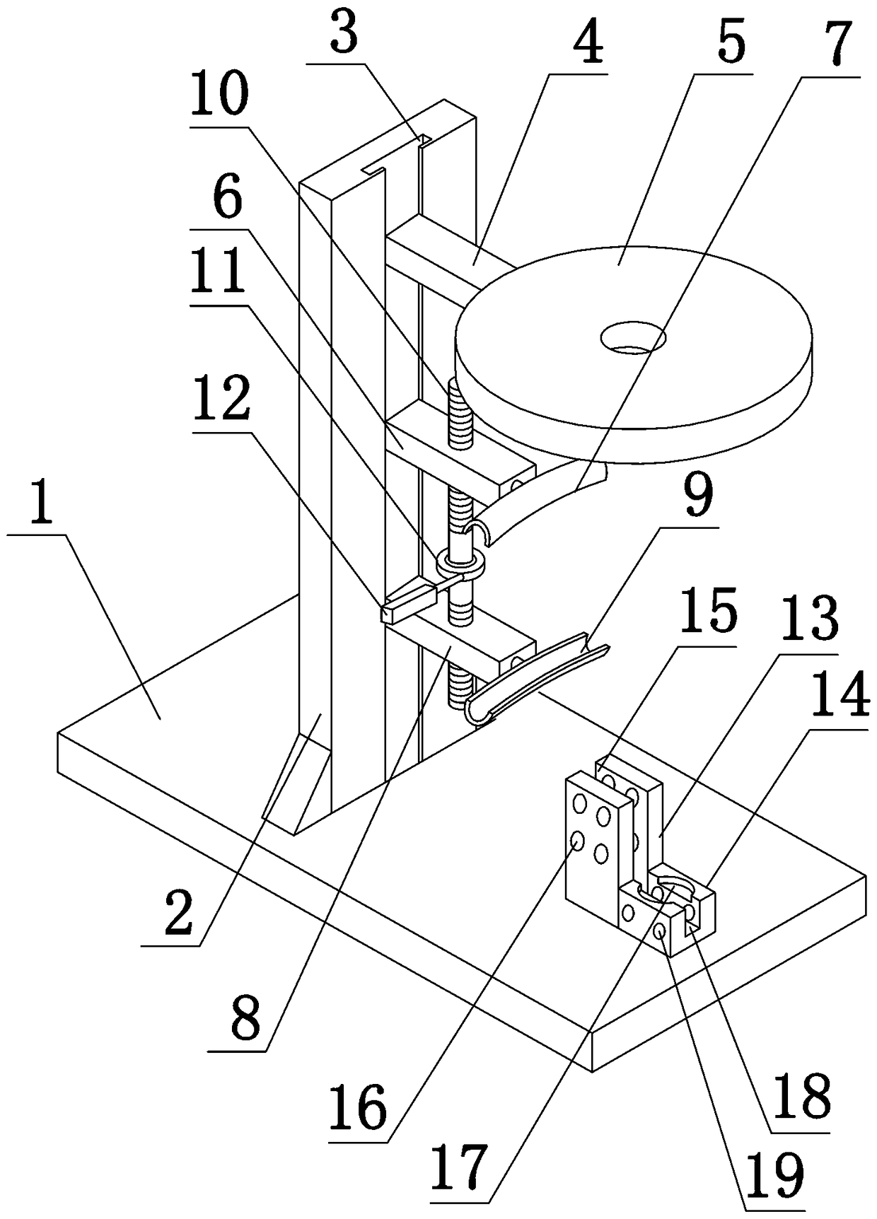
[0028] Such as figure 2 As shown, the present invention discloses an automobile shock absorbing set correction device, comprising a support base 1, the upper end surface of the support base 1 is fixedly connected to the vertical plate 2 and the boss, and the front end surface of the vertical plate 2 is provided with a guide rail 3, and the inside of the guide rail 3 is from top to bottom. The lower slide connects the limit pillar 4, the upper clamp and the lower fixture. The front end of the limit pillar 4 is welded and fixed with a pressure plate 5. The upper clamp includes an upper pillar 6 and an upper clip 7 that is rotatably connected to the front end of the upper pillar 6. The clip 7 can rotate freely, and the lower clamp includes the lower pillar 8 and the lower clip 9 that is rotatably connected to the front end of the lower pillar 8, that is, the lower clip 9 can rotate freely, and the upper clip 7 and the lower clip 9 are curved in the direction of extension. shape,...

Embodiment 2

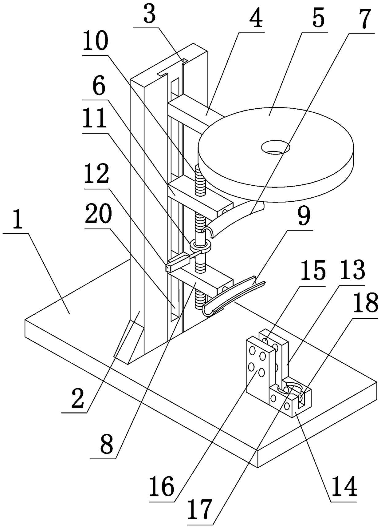
[0030] The structure of this embodiment is basically the same as that of Embodiment 1, the difference is: as Figure 3 to Figure 5 As shown, the bottom of the guide rail 3 is provided with a third through hole 20, the third through hole 20 is an elongated structure, and the rear end faces of the spacer pillar 4, the upper pillar 6 and the lower pillar 8 are all provided with a third threaded hole (not shown in the figure). ), the third threaded hole is internally threaded to connect the second threaded rod 21, the rear end of the second threaded rod 21 passes through the third through hole 20 and a back tightening nut 22 and a fixing nut 23 are installed at its end, the back tightening nut 22 is located on the fixed Between the nut 23 and the vertical plate 2; in addition, a groove 24 is provided on the lower end surface of the pressing plate 5, and a rubber buffer layer 25 is bonded in the groove.

Embodiment 3

[0032] The structure of this embodiment is basically the same as that of the implementation two, the difference is: as Figure 6 As shown, the edges of the upper clamp 7 and the lower clamp 9 are hinged semi-circular clamps 27, the following clamp 9 is an example, the semi-circular clamp 27 is made of steel and its two ends are respectively hung on the outer wall of the lower clamp 9 Then, when this structure is in use, the spring is further limited by the semi-annular clamp 27, thereby increasing the safety during the calibration process.


PUM


Abstract

The invention discloses a correction device for an automobile damping assembly. The correction device comprises a supporting base; a vertical plate and a boss are arranged on the supporting base; a guide way is arranged on the front end face of the vertical plate; a limiting supporting column, an upper clamp and a lower clamp are arranged in the guide way; the upper clamp comprises an upper supporting column and an upper clamping part; the lower clamp comprises a lower supporting column and a lower clamping part; the upper supporting column is provided with a first threaded hole in the vertical direction; the lower supporting column is provided with a second threaded hole in the vertical direction; the internal thread direction of the first threaded hole is opposite to that of the second threaded hole; a first threaded rod is arranged in both the first threaded hole and the second threaded hole; and a ratchet mechanism is arranged in the middle of the first threaded rod. According to the correction device for the automobile damping assembly, by means of the limiting supporting column, the upper clamp and the lower clamp arranged on the vertical plate, dampers which are differently sized can be limited, installation is simple, operation is convenient, and the correction device is suitable for correction operation of damping assemblies with different models and sizes.

Description

technical field [0001] The invention belongs to the technical field of automobile maintenance, and in particular relates to an automobile shock absorbing set correction device. Background technique [0002] The car shock absorber is one of the important parts of the car. It effectively reduces the vibration of the frame and the body during the running of the vehicle, which is of great significance to the smoothness and comfort of the car. The car shock absorber usually includes shock absorbers and Spring, during the long-term use of the vehicle, the shock-absorbing set is used as a buffer component to bear the impact force generated by the vibration of the vehicle body, and is a vulnerable part. Driving on roads with poor road conditions for a long time or due to bad driving habits (frequently stepping on the brakes and slamming on the accelerator) will cause irreversible deformation of the spring and shorten the spring stroke, which not only affects the comfort of the vehic...

Claims


Application Information

Patent Timeline
Patent Type & Authority Patents(China)
IPC IPC(8): B25B11/02
CPCB25B11/02
Inventor 刘华莉曹义孙斌
Owner UNIV FOR SCI & TECH ZHENGZHOU
Why Eureka
Try Eureka