Automatic cutting device

A technology of automatic cutting device and clamping device, which is applied in metal processing and other directions, can solve the problems of poor cutting length flexibility, hidden safety hazards of workers, and reduced cutting accuracy, etc., to achieve the effect of improving flexibility, avoiding failures and improving accuracy

Inactive Publication Date: 2017-05-24
刘程杰
View PDF0 Cites 3 Cited by
  • Summary
  • Abstract
  • Description
  • Claims
  • Application Information

AI Technical Summary

Problems solved by technology

However, the cutting device usually has a fixed length. When the cutting length is too long, a section of the material will extend out of the cutting device, which will cause safety hazards to the staff. Therefore, the cutting length is relatively fixed and the flexibility of the cutting length is poor; in addition, the material When cutting, due to mechanical vibration, the material will be displaced, resulting in a reduction in cutting accuracy

Method used


Image

  • Automatic cutting device

Examples


Embodiment 1

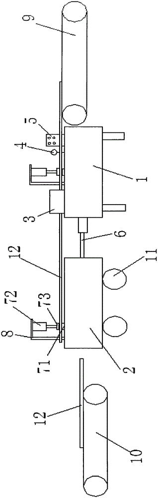
[0024] Such as figure 1 As shown, the embodiment of the present invention provides an automatic cutting device, including a first frame 1, a second frame 2, a controller 5, a first clamping device, a second clamping device, a cutting assembly 3, and a displacement sensor 4 . Telescopic device 6, the first frame 1 and the second frame 2 are sequentially arranged from front to back, the first frame 1 is provided with the cutting assembly 3, the first clamping device, and a displacement sensor 4. Controller 5; the second clamping device is provided on the second frame 2; the output of the displacement sensor 4 is connected to the controller 5, and the output of the controller 5 is respectively connected to the first clamp Holding device, second holding device, cutting assembly 3. The telescopic device 6 is located between the first frame 1 and the second frame 2 .

Embodiment 2

[0026] On the basis of Embodiment 1, the fixed end of the telescopic device 6 in this embodiment is arranged on the rear side of the first frame 1, and the telescopic end of the telescopic device 6 is arranged on the second frame 2 on the front side. The fixed end of the telescopic device 6 can also be arranged on the rear side of the second frame 2 , and the telescopic end of the telescopic device 6 can also be arranged on the front side of the first frame 1 .

Embodiment 3

[0028] On the basis of Embodiment 1 or 2, this embodiment is also provided with a pulley 11 at the bottom of the second frame 2, and the first clamping device and the second clamping device have the same structure, and both include the following Pressing device and lower clamping plate 71, described lower clamping plate 71 is arranged on the corresponding frame, and described pressing device is arranged on the top of described lower clamping plate 71.


PUM


Abstract

The invention discloses an automatic cutting device. The automatic cutting device comprises a first rack, a second rack, a controller, a first clamping device, a second clamping device, a cutting assembly, a displacement sensor and a telescopic device. The first rack and the second rack are sequentially arranged from front to rear. The cutting assembly and the first clamping device are arranged on the first rack. The second clamping device is arranged on the second rack. The displacement sensor is in output connection with the controller. The controller is in output connection with the first clamping device, the second clamping device and the cutting assembly. The telescopic device is located between the first rack and the second rack. The automatic cutting device has the beneficial effects of being high in cutting precision, flexibility and efficiency, capable of lowering the cutting strength and good in cutting safety and is applied to the technical field of cutting.

Description

technical field [0001] The invention relates to the field of mechanical automation, in particular to an automatic cutting device. Background technique [0002] Cutting is often required after processing materials such as steel, reinforcement, and wood. Traditional cutting includes worker cutting and mechanical cutting. Workers have good cutting stability and flexibility, but have the disadvantages of low cutting efficiency and high cutting strength. Mechanical cutting can improve cutting efficiency and reduce cutting strength. However, the cutting device usually has a fixed length. When the cutting length is too long, a section of the material will extend out of the cutting device, which will cause safety hazards to the staff. Therefore, the cutting length is relatively fixed, and the flexibility of the cutting length is poor; in addition, the material When cutting, due to mechanical vibration, the material will be displaced, resulting in a reduction in cutting accuracy. ...

Claims


Application Information

Patent Timeline
Patent Type & Authority Applications(China)
IPC IPC(8): B26D7/02B26D7/26B26D7/32
CPCB26D7/02B26D7/2628B26D7/32
Inventor 刘程杰
Owner 刘程杰
Why Eureka
Try Eureka