Power battery and high-voltage distribution box integrated control system for blade electric vehicle

An integrated control system and pure electric vehicle technology, applied in the direction of electric vehicle charging technology, electric vehicles, battery/fuel cell control devices, etc., can solve the problems of cost difference and high cost of new energy components, so as to save installation space and reduce usage Quantity and use of wire harnesses, and the effect of reducing production costs

Pending Publication Date: 2017-05-24
HENAN LIXIANG POWER TECH CO LTD
8 Cites 10 Cited by

AI-Extracted Technical Summary

Problems solved by technology

After a long period of research and comparison, we found that the cost difference between electric vehicles and traditional g...

Method used

The structure of the system of the present invention is as follows: after the battery core is arranged, the front space 37, the side space 36, and the rear space 35 are reserved, and the insulating plate is fixedly supported by bolts on the shell of the reserved space of the battery pack At the bottom, the relay is fixed on the insulating plate with bolts, and the wiring harness is arranged in an orderly manner through the side space 36, the front space 37, and the rear spa...

Abstract

The invention provides a power battery and high-voltage distribution box integrated control system for a blade electric vehicle. The system comprises a battery pack lower shell box with a battery pack internally installed. The battery pack lower shell box seals the battery pack through a battery pack upper shell cover and a battery pack fixing support. A power battery positive electrode and a power battery negative electrode are arranged in the battery pack lower shell box. A manual maintenance power-off switch is arranged between the power battery positive electrode and the power battery negative electrode. The power battery positive electrode is connected with the contact switch input end of an MCU pre-charging relay, the contact switch input end of a quick charging relay, the contact switch input end of a general positive relay, the contact switch input end of a slow charging relay and the contact switch input end of an electric heating relay in parallel through wires. The power battery negative electrode is connected with the contact switch input end of a general negative relay. The power battery and high-voltage distribution box integrated control system has the beneficial effects that the production cost of the electric vehicle can be reduced, the dead weight of the electric vehicle is reduced, and the installation space of the electric vehicle is saved.

Application Domain

Batteries circuit arrangementsCharging stations +6

Technology Topic

Electric heatingControl system +11

Image

  • Power battery and high-voltage distribution box integrated control system for blade electric vehicle
  • Power battery and high-voltage distribution box integrated control system for blade electric vehicle
  • Power battery and high-voltage distribution box integrated control system for blade electric vehicle

Examples

  • Experimental program(1)

Example Embodiment

[0018] In order to have a clearer understanding of the technical features, objectives and effects of the present invention, the specific embodiments of the present invention will now be described with reference to the accompanying drawings. In each figure, the same reference numerals represent the same components. In order to make the drawings concise, the drawings only schematically show the parts related to the invention, and they do not represent the actual structure of the product.
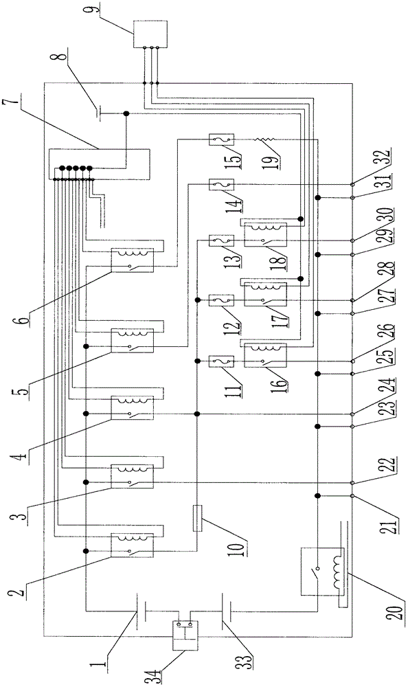
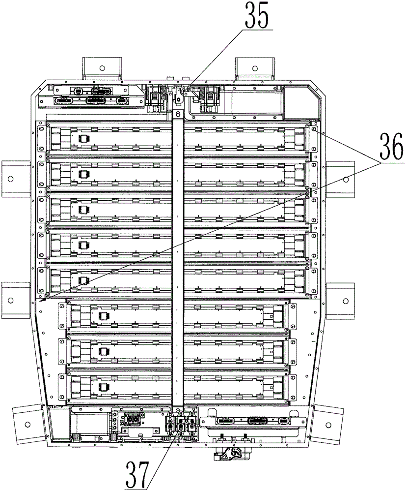
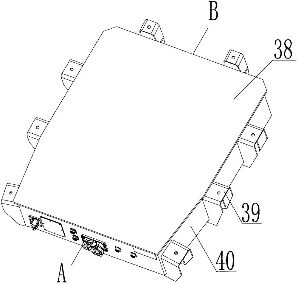
[0019] Such as figure 1 , 2 , 3, 4, 5, and 6, the present invention is a pure electric vehicle power battery and high-voltage distribution box integrated control system, including a battery pack lower shell box 40 with a battery pack installed inside, and the battery pack lower shell box The body 40 uses the battery pack upper shell cover 38 to seal the battery pack and realizes the fixation with the whole vehicle through the battery pack fixing bracket 39. The battery pack lower shell box 40 is provided with a power battery positive electrode 1 and a power battery negative electrode 33. , There is a manual maintenance power-off switch 34 between the power battery positive electrode 1 and the power battery negative electrode 33. The power battery positive electrode 1 is connected to the contact switch input terminal of the MCU pre-charge relay 2 and the contact switch input of the fast charge relay 3 through the wire. Terminal, the contact switch input terminal of the total positive relay 4, the contact switch input terminal of the slow charge relay 5 and the contact switch input terminal of the electric heating relay 6 are connected in parallel, and the power battery negative 33 and the contact switch input of the total negative relay 20 The contact switch output end of the total negative relay 20 is connected to the first negative contact 21, the second negative contact 23, the third negative contact 25, the fourth negative contact 27, and the fifth negative contact respectively through wires. 29 and the sixth negative contact 31 are connected in parallel. The contact switch output terminal of MCU precharge relay 2 is connected in series with precharge resistor 10. The precharge resistor 10 is connected to the contact switch output terminal of total positive relay 4 through a wire. The fast charge relay The contact switch output terminal 22 of 3 and the first negative contact 21 form a fast-charging positive and negative input circuit. The contact switch output 24 of the total positive relay 4 and the second negative contact 23 form the positive and negative output of the MCU. Loop, the contact switch output end of the slow charge relay 5 is connected in series with the first high-voltage fuse 14 through a wire, and the contact switch output end 32 of the slow charge relay 5 and the sixth negative contact 31 form the positive and negative input of the slow charge Circuit, the contact switch output terminal of the electric heating relay 6 is connected in series with the second high voltage fuse 15 and the electric heating wire 19 through the wire and forms an electric heating circuit with the contact switch output terminal 32 of the slow charge relay 5. The compressor relay 16 The contact switch input terminal of the DC/DC relay 17 and the contact switch input terminal of the PTC relay 18 are respectively connected to the third high-voltage fuse 11, the fourth high-voltage fuse 12 and the fifth high-voltage fuse through wires The compressor 13 is connected in series and connected in parallel with the contact switch output terminal of the main positive relay 4 through a wire. The contact switch output terminal 26 of the compressor relay 16 and the third negative contact 25 form the positive and negative output circuit of the compressor, DC/ The contact switch output terminal 28 of the DC relay 17 and the fourth negative contact 27 form a DC/DC positive and negative output circuit, and the contact switch output 30 of the PTC relay 18 and the fifth negative contact 29 form the positive and negative of the PTC Pole output circuit, the coil input end of the MCU precharge relay 2, the coil input end of the fast charge relay 3, the coil input end of the total positive relay 4, the coil input end of the slow charge relay 5, and the coil of the electric heating relay 6 Input terminal, the coil input terminal of the total negative relay 20, the coil input terminal of the compressor relay 16, and the coil output of the DC/DC relay 17. The input terminal and the coil input terminal of the PTC relay 18 are both connected to the power supply 8. The coil output terminal of the MCU precharge relay 2, the coil output terminal of the fast charge relay 3, the coil output terminal of the total positive relay 4, and the slow charge relay The coil output terminal of 5, the coil output terminal of the electric heating relay 6, and the coil output terminal of the total negative relay 20 are respectively connected to the high-voltage battery control unit 7. The coil output terminal of the compressor relay 16 and the DC/DC relay 17 The coil output terminal of the PTC relay 18 and the coil output terminal of the PTC relay 18 are respectively connected to the vehicle control unit 9; the first negative contact 21 and the contact switch output terminal 22 of the fast charge relay 3 are set in the lower case of the battery pack The first high-voltage dual-core connector 41 outside the body 40 is used as the fast charging input interface, and the second negative contact 23 and the contact switch output terminal 24 of the total positive relay 4 adopt the second set outside the lower casing 40 of the battery pack. The high-voltage dual-core connector 48 is used as the MCU output power interface. The third negative contact 25, the fourth negative contact 27, the fifth negative contact 29, and the sixth negative contact 31 are all set in the lower case 40 of the battery pack. The external first high-voltage four-core connector 44 serves as the negative circuit interface of the compressor relay 16, the DC/DC relay 17, the PTC relay 18 and the slow charge relay 5. The contact switch output terminal 26 of the compressor relay 16, DC/DC The relay 17 contact switch output terminal 28, the PTC relay 18 contact switch output terminal 30, and the slow charge relay 5 contact switch output terminal 32 all use the second high-voltage four-core connector 43 located outside the lower casing 40 of the battery pack. As the positive circuit interface, the coil of the internal relay of the high-voltage battery and the auxiliary low-voltage power supply required by the high-voltage battery control unit 7 adopt the low-voltage twelve-core connector 46 provided outside the lower casing 40 of the battery pack for the high-voltage battery pack For connection with the vehicle wiring harness, the CAN communication wiring harness between the high-voltage battery control unit 7 and other control units of the vehicle uses an eight-core connector 47 to connect the high-voltage battery pack and the vehicle wiring harness. The first high-voltage fuse 14, the second high-voltage fuse 15, the third high-voltage fuse 11, the fourth high-voltage fuse 12, and the fifth high-voltage fuse 13 are all high-voltage direct current fuses. The MCU precharge relay 2, fast charge relay 3, total positive relay 4, slow charge relay 5, electric heating relay 6, compressor relay 16, DC/DC relay 17, PTC relay 18, and total negative relay 20 are all High voltage DC relay. The third high-voltage fuse 11, the fourth high-voltage fuse 12, the fifth high-voltage fuse 13, the first high-voltage fuse 14 and the second high-voltage fuse 15 are all set inside the lower case 40 of the battery pack. On the bracket 49, the upper part of the safety bracket 49 is provided with a sealing rubber gasket 50 and a cover plate 51. A maintenance interface 42 is provided on the outside of the lower casing 40 of the battery pack. A front space 37, a rear space 35, and a side space 36 are provided inside the battery pack lower shell box 40. In the present invention image 3 A is side A, B is side B, Figure 4 for image 3 An enlarged view of the middle A side; Image 6 for image 3 An enlarged view of side B in the middle.
[0020] The structure of the system of the present invention is as follows: after the battery core is arranged, the front space 37, the side space 36, and the rear space 35 are reserved, and the insulating plate is fixed and supported on the bottom of the shell of the reserved space of the battery pack by bolts, and then The relay is bolted to the insulating board, and the wiring harness is arranged in an orderly manner through the side space 36, the front space 37 and the rear space 35, and is fixed on the panel wall of the battery pack shell by wire clips or cable ties. Such as image 3 As shown, the battery pack upper shell cover 38 and the battery pack lower shell box body 40 are combined and sealed, and the battery pack fixing bracket 39 is welded to the battery pack lower shell box body 40, and the battery pack upper shell cover 38 and the lower shell box The body 40 and the fixing bracket 39 realize the sealing of the battery pack and the installation and fixation with the whole vehicle.
[0021] The working mode of the system of the present invention is:
[0022] 1. After the high-voltage battery is assembled with the whole vehicle, after the key switch is activated, the vehicle control unit 9 and the high-voltage battery control unit 7 begin to communicate, and the high-voltage battery control unit 7 controls the MCU precharge relay 2 and the total negative relay 20 to close the contact switch. After the pre-charging is completed, the quick-charge relay 3 contact switch is closed, and then the MCU pre-charging relay 2 contact switch is disconnected, which realizes the pre-charging function of the high-voltage battery before providing high-voltage output to the MCU.
[0023] 2. After the vehicle is started, the vehicle control unit 9 controls the contact switches of the compressor relay 16, the DC/DC relay 17 and the PTC relay 18 to close or open to realize the control of the compressor, DC/DC, and PTC output power.
[0024] 3. After entering the fast charging mode, the high-voltage battery control unit 7 controls the quick-charge relay 3 and the total negative relay 20 to close the contact switches to provide an input circuit for the high-voltage battery.
[0025] 4. After entering the slow charge charging mode, the high-voltage battery control unit 7 controls the contact switches of the total negative relay 20 and the slow-charge relay 5 to close, providing an input circuit for the high-voltage battery; when the temperature is too low, close the electric heating relay 6 The contact switch and the contact switch of the total negative relay 20 are disconnected, so that the charger is used as the power source to heat the high-voltage battery.
[0026] The wiring mode of the system of the present invention is: figure 1 , 4 , 5, 6, the first negative contact 21 and the contact switch output terminal 22 of the quick charge relay 3 use the first high-voltage dual-core connector 41 as the quick charge input interface; the second negative contact 23 and the total positive relay The contact switch output terminal 24 of 4 uses the second high-voltage dual-core connector 48 as the MCU output power interface; the third negative contact 25, the fourth negative contact 27, the fifth negative contact 29 and the sixth negative contact 31 The first high-voltage four-core connector 44 is used as the negative circuit interface of the compressor relay 16, the DC/DC relay 17, the PTC relay 18 and the slow charge relay 5; the contact switch output terminal 26, DC/DC of the compressor relay 16 The relay 17 contact switch output terminal 28, the PTC relay 18 contact switch output terminal 30, and the slow charge relay 5 contact switch output terminal 32, adopt the second high-voltage four-core connector 43 as the positive loop interface. The coil of the internal relay of the high-voltage battery and the auxiliary low-voltage power supply required by the high-voltage battery control unit 7 use a low-voltage twelve-core connector 46 to connect the high-voltage battery pack and the wiring harness of the vehicle; the high-voltage battery control unit 7 is connected to the vehicle The CAN communication harness of other control units uses an eight-core connector 47 to connect the high-voltage battery pack to the wiring harness of the vehicle; the compressor high-voltage fuse 11, DC/DC high-voltage fuse 12, and PTC high-voltage fuse 13, slow charging The high-voltage fuse 14 and the electric heating high-voltage fuse 15 are placed on the safety bracket 49, and the sealing rubber gasket 50 is matched with the cover plate 51 to realize the sealing of the repair interface 42 and the entire battery pack lower case 40.
[0027] In the description of the present invention, it should be noted that, unless otherwise clearly defined and limited, the terms "connected", "connected", etc. should be interpreted broadly. For example, they may be fixedly connected, integrally connected, or Removable connection; it can also be the internal communication between the two components; it can be directly connected or indirectly connected through an intermediate medium. For those of ordinary skill in the art, the specific conditions of the above terms in the present invention can be understood according to the specific situation. meaning. The above detailed description is only a specific description of the feasible embodiments of the present invention. They are not intended to limit the scope of protection of the present invention. All equivalent implementations, changes and modifications made without departing from the technical spirit of the present invention shall include Within the protection scope of the present invention.

PUM

no PUM

Description & Claims & Application Information

We can also present the details of the Description, Claims and Application information to help users get a comprehensive understanding of the technical details of the patent, such as background art, summary of invention, brief description of drawings, description of embodiments, and other original content. On the other hand, users can also determine the specific scope of protection of the technology through the list of claims; as well as understand the changes in the life cycle of the technology with the presentation of the patent timeline. Login to view more.

Similar technology patents

WIFI (Wireless Fidelity) network device and WIFI network access method

InactiveCN105228152Aeasy connectionEasy authentication connection
Owner:ZHUHAI JIELI TECH

Solar cell and supercapacitor integrated device and manufacturing method thereof

InactiveCN108987118Aeasy connectionReduce device size
Owner:SHANGHAI INTEGRATED CIRCUIT RES & DEV CENT

Curved surface image sensor, and welding structure of circuit board and camera module thereof

InactiveCN107995399AShorten the connection distanceReduce connection impedance
Owner:TRULY OPTO ELECTRONICS

Intelligent computer system capable of real-time interaction

Owner:HENAN MECHANICAL & ELECTRICAL ENG COLLEGE

Indirect heat exchange type ice crystal spread-resistant device

InactiveCN102012139Aeasy connection
Owner:GUANGZHOU SENYO THERMAL STORAGE TECH

Classification and recommendation of technical efficacy words

  • Shorten the connection distance
  • easy connection

Curved surface image sensor, and welding structure of circuit board and camera module thereof

InactiveCN107995399AShorten the connection distanceReduce connection impedance
Owner:TRULY OPTO ELECTRONICS

Shearing type lead damper

Owner:BEIJING UNIV OF TECH

Pile holding machine

Owner:WUHAN MARINE MACHINERY PLANT

CO2 displacement simulated testing method

ActiveCN108414727Aeasy connectionGuarantee system security
Owner:CHINA UNIV OF MINING & TECH
Why Eureka
Try Eureka