
Silicon rod loading and unloading transferring equipment

A technology of equipment and silicon rods, which is applied in the direction of transportation and packaging, conveyor objects, conveyors, etc., can solve problems such as increased production costs, waste of manpower and material resources, and damage to silicon rods, so as to improve work efficiency, reduce workload, and reduce cost effect

Active Publication Date: 2017-05-24
TIANJIN LONYU SCI & TECH PROGRESS
View PDF7 Cites 3 Cited by
  • Summary
  • Abstract
  • Description
  • Claims
  • Application Information

AI Technical Summary

Problems solved by technology

[0002] The single crystal of silicon is a crystal with a basically complete lattice structure. It is a good semiconducting material and is used in the manufacture of semiconductor devices, solar cells, etc. With the advancement of scientific and technological productivity, the use of its scope of use is increasing. The higher it is, the proportion of various products gradually increases, and the monocrystalline silicon currently used in various fields is generally cut and processed by larger silicon rods, cut into different sizes and applied to various fields, while the existing When the silicon rods are processed, they are all carried by manpower and placed on the corresponding storage racks or processing equipment. Due to the heavy weight of the silicon rods and the high storage racks, it is inevitable that they will collide with the shelves when they are transported up and down. , resulting in damage to silicon rods and waste, and manual handling of silicon rods up and down on high shelves wastes manpower and material resources, and the efficiency is low, which is not conducive to increasing production costs

Method used


Image

  • Silicon rod loading and unloading transferring equipment
  • Silicon rod loading and unloading transferring equipment
  • Silicon rod loading and unloading transferring equipment

Examples


Embodiment Construction

[0033] It should be noted that, in the case of no conflict, the embodiments of the present invention and the features in the embodiments can be combined with each other.

[0034] In describing the present invention, it should be understood that the terms "center", "longitudinal", "transverse", "upper", "lower", "front", "rear", "left", "right", " The orientations or positional relationships indicated by "vertical", "horizontal", "top", "bottom", "inner" and "outer" are based on the orientations or positional relationships shown in the drawings, and are only for the convenience of describing the present invention and Simplified descriptions, rather than indicating or implying that the device or element referred to must have a particular orientation, be constructed and operate in a particular orientation, and thus should not be construed as limiting the invention. In addition, the terms "first", "second", etc. are used for descriptive purposes only, and should not be understood ...


PUM


Abstract

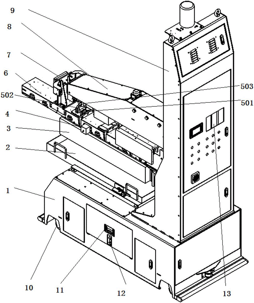
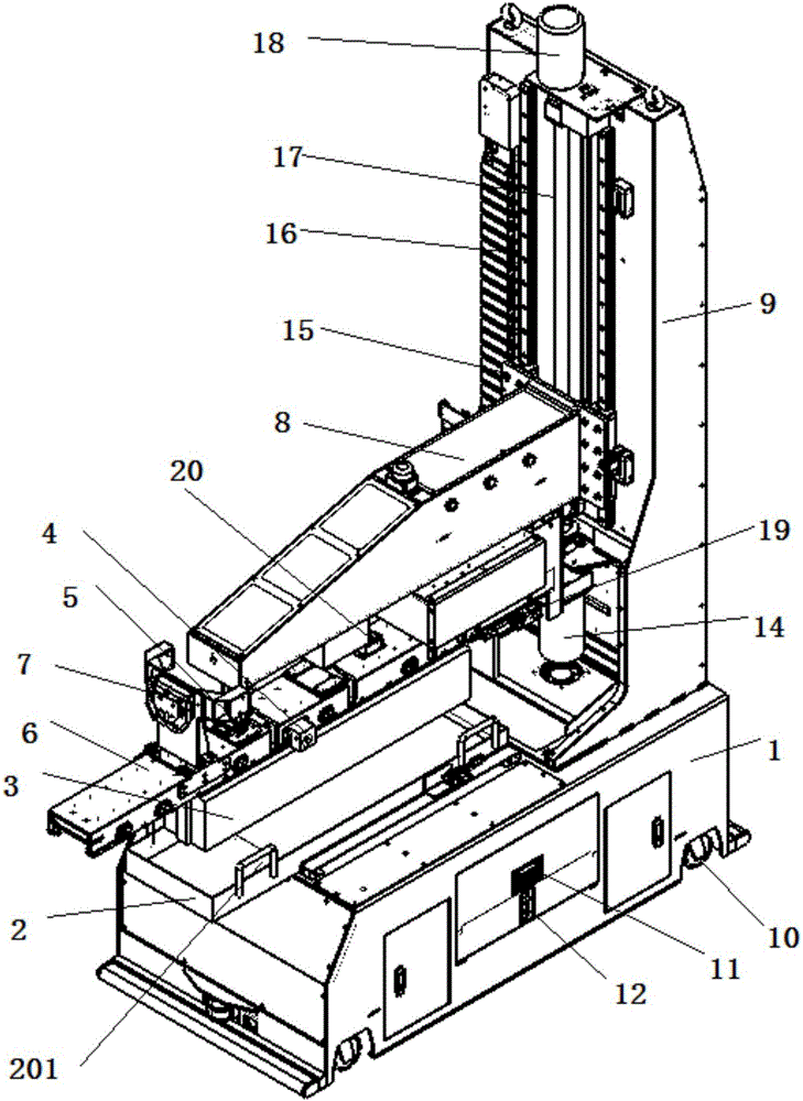
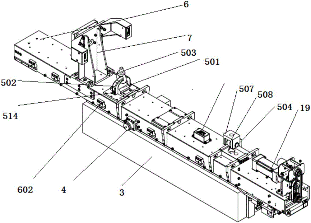
The invention provides silicon rod loading and unloading transferring equipment which comprises a base and a support, wherein the support is placed on and fixedly connected with the base; one side wall of the support is connected with a manipulator in a sliding way through a first sliding mechanism; the bottom of the manipulator is flexibly connected with a cantilever through a rotating mechanism; a gripping jaw is arranged at the bottom of the cantilever; and the gripping jaw is connected with the cantilever in a sliding way through a second sliding mechanism. According to the silicon rod loading and unloading transferring equipment, the sliding gripping jaw is adopted to grip or release a silicon rod to finish loading or unloading of the silicon rod, manual handling is not needed, quick and accurate positioning and automatic control are realized, the working efficiency is increased, and the cost is reduced.

Description

technical field [0001] The invention belongs to the field of photovoltaic new energy equipment, and in particular relates to a transfer equipment for loading and unloading silicon rods. Background technique [0002] The single crystal of silicon is a crystal with a basically complete lattice structure. It is a good semiconducting material and is used in the manufacture of semiconductor devices, solar cells, etc. With the advancement of scientific and technological productivity, the use of its scope of use is increasing. The higher it is, the proportion of various products gradually increases, and the monocrystalline silicon currently used in various fields is generally cut and processed by larger silicon rods, cut into different sizes and applied to various fields, while the existing When the silicon rods are processed, they are all carried by manpower and placed on the corresponding storage racks or processing equipment. Due to the heavy weight of the silicon rods and the h...

Claims


Application Information

Patent Timeline
IPC IPC(8): B65G47/90
CPCB65G47/902B65G47/905B65G2201/0217
Inventor 任志勇杨国安彭玉佩刘强
Owner TIANJIN LONYU SCI & TECH PROGRESS
Learn More