
a valve guide

A valve guide and body technology, used in the lubrication of valve devices, valve accessories, machines/engines, etc., can solve the problems of oil burning, poor lubrication conditions, shortened life of parts, etc., to prevent vibration, improve the lubrication environment, and increase the life. Effect

Active Publication Date: 2022-08-05
CHANGSHA UNIVERSITY OF SCIENCE AND TECHNOLOGY
View PDF6 Cites 0 Cited by
  • Summary
  • Abstract
  • Description
  • Claims
  • Application Information

AI Technical Summary

Problems solved by technology

The operating temperature of the valve guide is relatively high, and the lubrication conditions are poor. The valve stem and the valve guide hole are lubricated by the oil splashed when the valve train is working.
In the current valve guide technology, due to the reciprocating linear motion of the valve in the valve guide, there will be a phenomenon of increased wear of the valve and valve guide due to the reduction of lubricating oil, and the phenomenon of "burning engine oil" will occur if there is too much lubricating oil, which will cause the dynamic performance of the internal combustion engine. , economy, reliability deterioration, environmental pollution and shortened life of related parts
[0003] In view of the above problems, in order to reasonably solve the carbon deposit phenomenon caused by "burning engine oil" and "oil leakage" in the cylinder, the present invention designs a valve guide device that can realize the continuous unidirectional spreading and transportation of fluid without external power, so as to prevent Occurrence of "burning engine oil" and "exhaust pipe oil leakage" faults

Method used


Image

  • a valve guide
  • a valve guide
  • a valve guide

Examples


Embodiment Construction

[0015] The present invention will be further described below with reference to the accompanying drawings and embodiments.

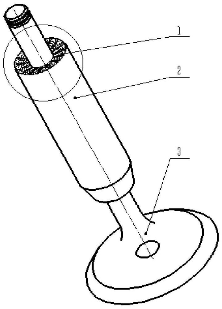
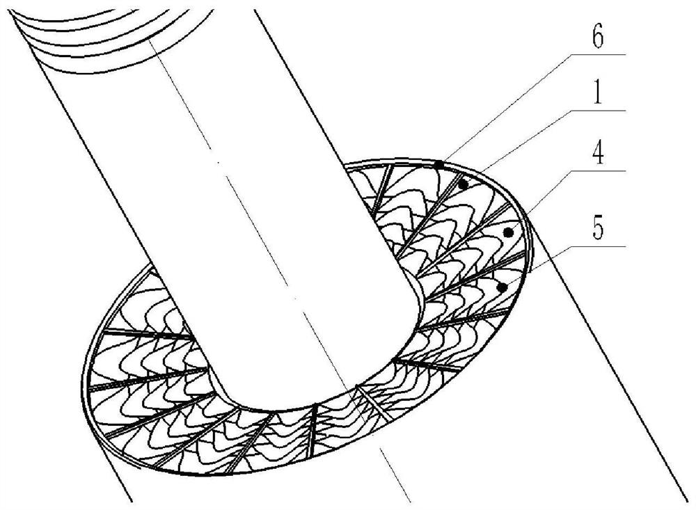
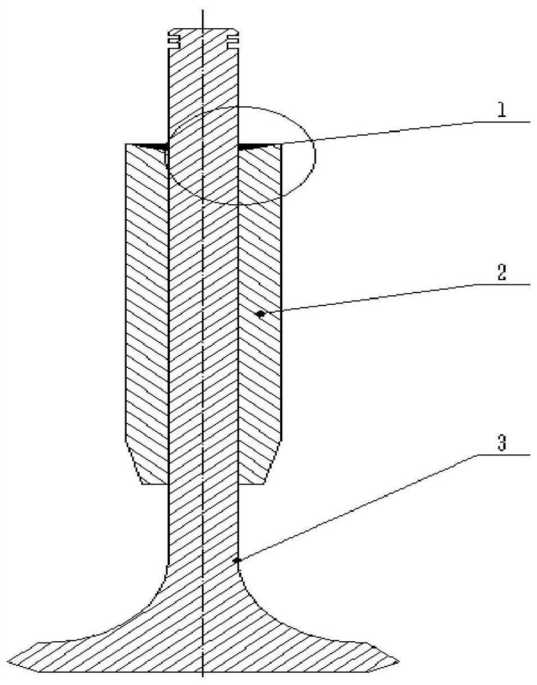
[0016] The working temperature of the valve guide is relatively high, and the lubricating conditions are poor. The oil splashed when the valve train works is used to lubricate the valve rod and the valve guide hole. The invention can solve the problem of poor lubrication caused by too little or too much lubricating fluid. phenomenon, such as figure 1 , figure 2 , image 3 , Figure 4 and Figure 5 As shown, the present invention includes a valve guide body 2 and a valve stem 3, the valve stem 3 is installed inside the valve guide body 2, the upper end surface of the valve guide body 2 is a slope inclined from the outer edge to the center, and the slope surface has a plurality of The center of the valve guide body 2 is the starting point and the secondary grooves 1 radiating outward in an array and adjacent to each other are distributed in each second...


PUM


Abstract

The invention discloses a valve guide. The upper end surface of the valve guide body (2) is a slope inclined from the outer edge to the center, and the slope surface has a plurality of lines starting from the center of the valve guide body (2). The secondary grooves (1) radiating outward in an array and adjacent to each other are distributed in each of the secondary grooves (1) starting from the center of the valve guide body (2). A plurality of wedge-shaped blind holes that radiate outward in a uniform distribution in an array structure and are distributed in a gradient stack to form a wedge-shaped included angle, the wedge-shaped edge (5) of each of the wedge-shaped blind holes is arched, and the edge is sharp, and its opening is along the The secondary groove (1) faces the inner center of the valve guide body (2); the upper end face of the valve guide body (2) is provided with an arched boss (6) on the circumferential edge. The invention is a valve guide which can realize continuous unidirectional spreading and conveying of fluid without external power, thereby improving lubricating environment.

Description

technical field [0001] The present invention relates to a valve guide. Background technique [0002] The function of the valve guide is to guide the movement of the valve, to ensure the linear reciprocating motion of the valve, so that the valve and the valve seat or valve seat ring can be properly fitted. The working temperature of the valve guide is high, and the lubrication conditions are poor. The oil splashed when the valve train works to lubricate the valve stem and the valve guide hole. The current valve guide technology, because the valve reciprocates in a straight line in the valve guide, the reduction of lubricating oil will cause the wear of the valve and the valve guide to increase. If the lubricating oil is too much, the phenomenon of "burning oil" will occur, which will cause the dynamic performance of the internal combustion engine. , Deterioration of economy, reliability, environmental pollution and shortened life of related parts. [0003] In view of the a...

Claims


Application Information

Patent Timeline
Patent Type & Authority Patents(China)
IPC IPC(8): F01L3/08F01M9/10
CPCF01L3/08F01M9/103
Inventor 胡林陈凯黄晶刘志强吴钢
Owner CHANGSHA UNIVERSITY OF SCIENCE AND TECHNOLOGY
Learn More