
Dual-channel electric supercharger

An electric supercharger, dual-channel technology, applied in the direction of engine components, machines/engines, mechanical equipment, etc., can solve problems such as small pressure ratio and air mass flow rate, increase the manufacturing cost of the supercharging system, and low compression efficiency of the compressor , to achieve the effect of high compression efficiency, easy automatic coupling and low manufacturing cost

Active Publication Date: 2017-05-24
CHONGQING IND POLYTECHNIC COLLEGE
View PDF5 Cites 0 Cited by
  • Summary
  • Abstract
  • Description
  • Claims
  • Application Information

AI Technical Summary

Problems solved by technology

Traditional exhaust gas turbocharging, mechanical supercharging or air wave supercharging not only has a complex system and high manufacturing cost, but also inevitably has problems such as insufficient low-speed torque and lagging acceleration response due to its working principle
[0003] In order to overcome the deficiencies of the traditional supercharging technology, most of them currently use the structure of the electric auxiliary supercharging system or the TSI dual supercharging system, which further complicates the supercharging system and further increases the manufacturing cost of the supercharging system.
In addition, existing electric superchargers have power supply problems, motor problems, low compression efficiency of the compressor, small pressure ratio and air mass flow rate, etc.

Method used


Image

  • Dual-channel electric supercharger
  • Dual-channel electric supercharger
  • Dual-channel electric supercharger

Examples


Embodiment

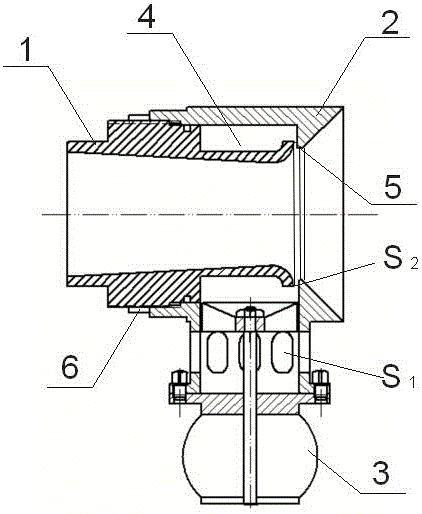
[0025] Example: see figure 1 , a dual-channel electric supercharger, comprising a main intake pipe 1 , an adjustable intake pipe 2 and an electric compressor 3 . An annular groove 4 is formed on the outside of the rear part of the main air intake pipe 1 , and the annular groove 4 runs through the rear end of the main air intake pipe 1 . The rear end of the main air intake pipe 1 expands and bends outwards, so that the section of the main air intake pipe 1 rear end is an arc section, and the inner diameter of the main air intake pipe 1 gradually increases from the rear end to the front end, so that the main air intake pipe 1 The inner hole of 1 is in the shape of a (hyperboloid) cone as a whole.

[0026] The inner hole of the adjustable intake pipe 2 is stepped, and the inner diameter of the front part is greater than the inner diameter of the rear part. The front end of the adjustable intake pipe 2 is inserted into the main intake pipe 1 from the rear end of the main intake p...


PUM


Abstract

The invention discloses a dual-channel electric supercharger. The dual-channel electric supercharger comprises a gas inlet main pipeline, an adjustable gas inlet pipe and an electric gas compressor; an annular groove surrounding the gas inlet main pipeline by a circle is arranged on the outer side of the rear portion of the gas inlet main pipeline, and penetrates the rear end of the gas inlet main pipeline; the rear end of the gas inlet main pipeline is enlarged and bent to the outer side; the adjustable gas inlet pipe is connected with the front portion of the gas inlet main pipeline in a threaded manner so that an annular gas cavity can be formed between the front portion of the adjustable gas inlet pipe and the annular groove; when gas in the annular gas cavity flows out of an annular gas outlet, the gas can flow along the arc-shaped inner wall of the rear end of the gas inlet main pipeline, and therefore a Coanda Effect can be generated; and the electric gas compressor is connected with the front portion of the adjustable gas inlet pipe, and is communicated with the interior of the adjustable gas inlet pipe, and gas can be introduced into the annular gas cavity by the electric gas compressor. The dual-channel electric supercharger is simple in structure, low in cost, faster in response, high in gas compressing efficiency and capable of performing supercharging adjustment according to engines different in discharging capacity, and therefore the adaptive capacity is higher.

Description

technical field [0001] The invention relates to the technical field of air intake supercharging of automobile engines, in particular to a dual-channel electric supercharger. Background technique [0002] At present, the simplification of automobile engines and the supercharging of air intake systems have become the trend of the global automobile industry. Traditional exhaust gas turbocharging, mechanical supercharging or air wave supercharging not only has a complex system and high manufacturing cost, but also inevitably has problems such as insufficient low-speed torque and lagging acceleration response due to the characteristics of its working principle. [0003] In order to overcome the deficiencies of the traditional supercharging technology, most of them currently use an electric auxiliary supercharging system framework or a TSI dual supercharging system framework, which further complicates the supercharging system and further increases the manufacturing cost of the sup...

Claims


Application Information

Patent Timeline
IPC IPC(8): F02B39/10
CPCF02B39/10
Inventor 彭钿忠曹晓峰麻建坐
Owner CHONGQING IND POLYTECHNIC COLLEGE
Learn More