
Evaporator dedusting and defrosting system of air source heat pump

A technology of air source heat pump and evaporator, which is applied in the direction of evaporator/condenser, heat pump, lighting and heating equipment, etc., can solve the problem of low defrosting efficiency, low heat exchange efficiency between medium and outside air, easy frosting or freezing and other problems, to achieve the effect of improving heat exchange efficiency, good heat exchange efficiency, and reducing energy consumption

Inactive Publication Date: 2017-05-24
硕楠
View PDF6 Cites 9 Cited by
  • Summary
  • Abstract
  • Description
  • Claims
  • Application Information

AI Technical Summary

Problems solved by technology

The working efficiency of the air source heat pump is greatly affected by external environmental factors. Since the pipeline of the evaporator is exposed to the external environment, the surface of the coil and fins is easy to be covered with dust after long-term use, which makes the medium in the evaporator tube and the outside air The heat exchange efficiency is reduced, which increases the energy consumption of the air source heat pump
Moreover, in the cold winter, the surface of the coil and fins is prone to frost or ice. Due to the blocking effect of the frost on the air, the working efficiency of the air source heat pump is greatly reduced. The existing deicing principle is to use the heat in the water tank to The energy of water is used for defrosting, and the defrosting efficiency is relatively low

Method used


Image

  • Evaporator dedusting and defrosting system of air source heat pump
  • Evaporator dedusting and defrosting system of air source heat pump
  • Evaporator dedusting and defrosting system of air source heat pump

Examples


Embodiment Construction

[0017] The present invention will be further described below in conjunction with the accompanying drawings and embodiments.

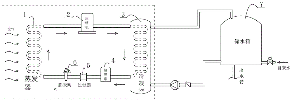
[0018] Such as figure 1 As shown in , a schematic structural diagram of an air source heat pump is given, which is composed of an evaporator 1, a compressor 2, a condenser 3, a liquid storage tank 4, a filter 5 and an expansion valve 6, and the compressor 2 is arranged between the outlet of the evaporator and the On the pipeline connected between the pipeline inlets of the condenser, the liquid storage tank 4, the filter 5 and the expansion valve 6 are sequentially arranged on the pipeline between the condenser pipeline outlet and the evaporator inlet. After the medium absorbs the heat from the outside in the evaporator 1, the compressor 2 is used to increase the pressure and temperature, and the heat is transferred to the circulating water in the water storage tank 7 through the condenser 3, so as to realize the heat transfer from the air to the circul...


PUM


Abstract

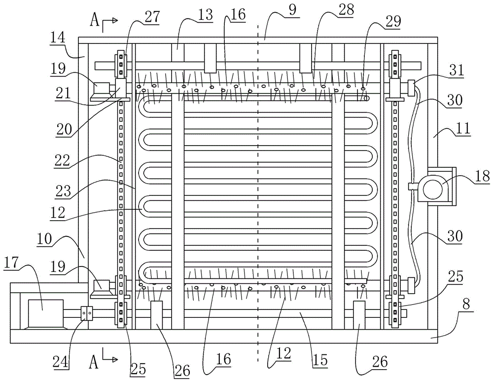
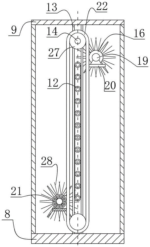
The invention discloses an evaporator dedusting and defrosting system of an air source heat pump. The system comprises a bracket, an upper shaft, a lower shaft, two hollow lifting pipes, a lifting motor, a rotary motor and an air heater and is characterized in that the upper shaft and the lower shaft are fixed on the bracket; upper chain wheels are arranged at two ends of the upper shaft; lower chain wheels are fixed at two ends of the lower shaft; the upper chain wheels and the lower chain wheels carry out transmission through chains; the lifting pipes are fixed on the chains; bristles are fixed on the outer surfaces of the lifting pipes; vent holes are uniformly formed in the outer surfaces of the lifting pipes; air outlets of the air heater communicate with inner cavities of the lifting pipes via a breather pipe; and the lifting motor drives the lower shaft to rotate to drive a chain transmission system to drive the bristles to sweep the surfaces of a coil and fins in a reciprocating manner, and a draught fan is adopted for blowing dust to ensure that an evaporator has excellent heat exchanging efficiency during working. Hot gas sprayed out of the vent holes in the lifting pipes also can be utilized to defrost and deice the surfaces of the coil and the fins, so that the heat exchanging efficiency of the evaporator in frost weather is improved, and energy consumption of the air source heat pump is further reduced.

Description

technical field [0001] The present invention relates to an air source heat pump evaporator dust removal and frost removal system, more specifically, to an air source heat pump evaporator dust removal and frost removal system which utilizes bristles and cold air to remove dust and hot air to remove frost. Background technique [0002] The air source heat pump is composed of compressor, evaporator, condenser, liquid storage tank, expansion valve and other devices. The medium circulates in the system under the action of the compressor. The working principle is: the liquid medium absorbs the air in the evaporator The heat energy is converted into a gaseous state; then, the medium passes through the compressor to complete the pressure increase of the gaseous state, and enters the condenser to transfer its own high-temperature heat to the circulating water, and at the same time it is transformed into a liquid, and then enters the evaporator again through the expansion valve In ord...

Claims


Application Information

Patent Timeline
IPC IPC(8): F25B39/02F25B47/02F25B30/02F25B30/06
CPCF25B30/02F25B30/06F25B39/02F25B47/02
Inventor 硕楠
Owner 硕楠
Learn More