Electronic expansion valve and its seat assembly

An electronic expansion valve and valve seat technology, applied in the field of control valves, can solve the problems of easy noise generation, high fluid turbulence intensity, noise, etc., and achieve the effect of avoiding noise and reducing turbulent flow intensity

Active Publication Date: 2019-11-15
ZHEJIANG SANHUA INTELLIGENT CONTROLS CO LTD
View PDF17 Cites 0 Cited by
  • Summary
  • Abstract
  • Description
  • Claims
  • Application Information

AI Technical Summary

Problems solved by technology

Therefore, when the system is in the cooling state, the refrigerant flows from the inner cavity of the valve seat through the four communication holes 113 into the inner cavity of the valve core seat 11, that is, the refrigerant flows through the process of splitting and then parallel flow, and because the four communication holes 113 and the refrigerant flow If the distances between the inlets (that is, the ports of the second connecting pipe 14) are not equal, there will be differences in the flow velocity and flow direction of the refrigerant flowing through the four communication holes 113, which will cause the refrigerant to form turbulent flow in the inner cavity of the valve core seat, and the fluid turbulence intensity will be high. , prone to noise when flowing through the valve port
When the system is in the heating state, the refrigerant flows into the inner cavity of the valve core seat from the valve port, flows into the inner cavity of the valve seat through four communication holes 113 and then flows to the second connecting pipe 14, because the four communication holes 113 and the refrigerant outlet (That is, the ports of the second connecting pipe 14) are not equal in distance, which will cause the four communication holes 113 to have different pressures on the side of the valve seat cavity, and the refrigerant will easily form turbulent flow after being split and flow together, resulting in noise

Method used


Image

  • Electronic expansion valve and its seat assembly
  • Electronic expansion valve and its seat assembly
  • Electronic expansion valve and its seat assembly

Examples


Embodiment Construction

[0030] In order to enable those skilled in the art to better understand the technical solutions of the present invention, the present invention will be further described in detail below in conjunction with the accompanying drawings and specific embodiments.

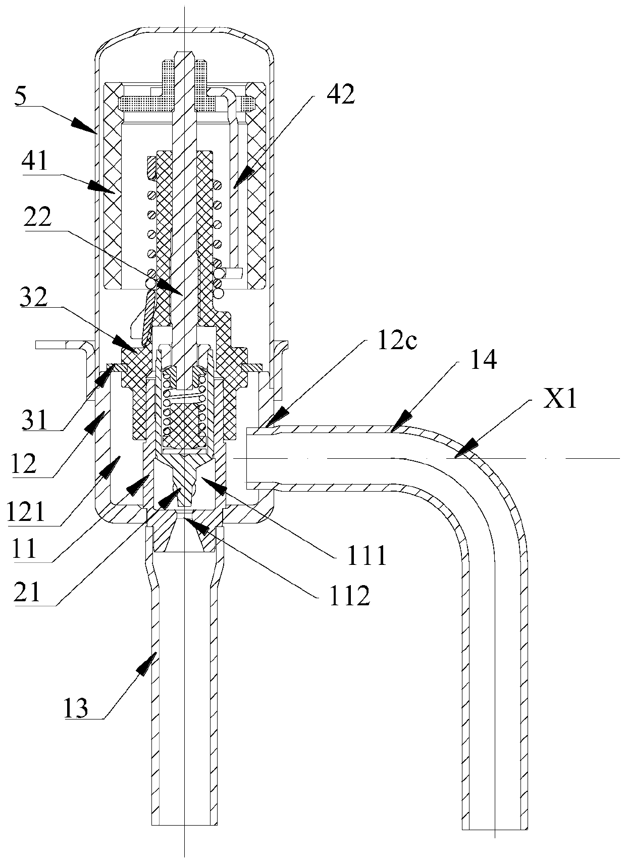
[0031] Please refer to image 3 , image 3 It is a structural schematic diagram of the seat assembly of the electronic expansion valve provided by the present invention.

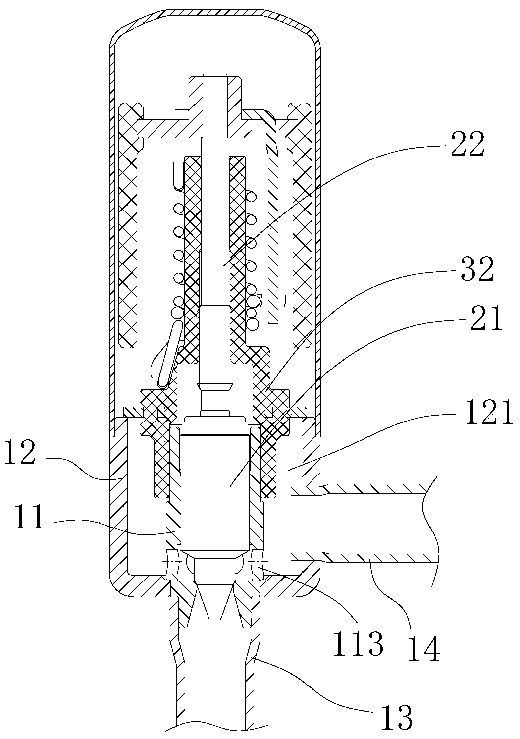
[0032] The electronic expansion valve provided by the present invention includes a valve seat assembly, a nut assembly, a valve needle screw assembly, a magnetic rotor assembly and a coil assembly.

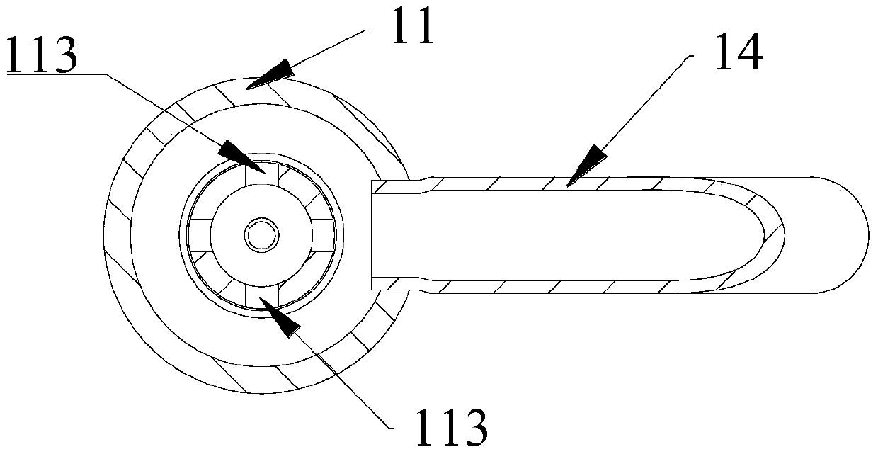
[0033] The valve seat assembly includes a valve core seat 11 and a valve seat 12 . The valve seat 12 is a substantially cylindrical structure with a matching hole on the bottom of the valve core seat, and a first valve cavity 121 is formed inside it. In this embodiment, the valve seat assembly further includes a first connecting pipe 13 and a second conn...


PUM


Abstract

The present invention provides a valve seat assembly of an electronic expansion valve, which is characterized in that it includes a valve seat provided with a first valve cavity and a substantially cylindrical valve core seat with a valve port fixed on the valve seat, The valve core seat forms the second valve cavity; the first connecting pipe and the second connecting pipe are fixedly connected with the valve seat; two communication holes are arranged on the circumferential side wall of the valve core seat, and the communication holes will The second valve chamber communicates with the first valve chamber; the two communication holes are symmetrically distributed along the first central axis of the second connecting pipe, and the distance between the two communicating holes and the second connecting pipe is equal. The present invention also provides an electronic expansion valve using the above-mentioned valve seat assembly. In the electronic expansion valve and the valve seat assembly thereof provided by the present invention, the refrigerant is not easy to generate turbulent flow, and the intensity of turbulent flow is reduced, thus avoiding the generation of noise.

Description

technical field [0001] The invention relates to the technical field of control valves, in particular to an electronic expansion valve for regulating fluid flow. Background technique [0002] In various refrigeration and heating equipment such as air conditioners, refrigerators, heat pump water heaters, etc., electronic expansion valves are usually used to regulate the flow of fluids. In addition, electronic expansion valves can also be used as pilot valves in solenoid valves. [0003] The electronic expansion valve usually includes a valve seat assembly, a nut assembly, a valve needle screw assembly, and a rotor assembly. The valve seat assembly usually includes a valve seat and a connecting pipe. The valve seat has a valve port, and the valve seat and the connecting pipe are usually welded together to form a valve. The seat assembly, the valve needle of the valve needle screw assembly is installed in the nut of the nut assembly. [0004] In order to solve the problem of c...

Claims


Application Information

Patent Timeline
Patent Type & Authority Patents(China)
IPC IPC(8): F25B41/06F25B41/34
CPCY02B30/70
Inventor 不公告发明人
Owner ZHEJIANG SANHUA INTELLIGENT CONTROLS CO LTD
Why Eureka
Try Eureka