Textile negative pressure dust collection and drying device

A drying device and technology for textiles, applied in the directions of drying, drying machine, drying gas arrangement, etc., can solve the problems of residue, inconvenient drying work, affecting the quality of textiles, etc., to accelerate drying speed and promote absorption. dust effect

Active Publication Date: 2017-05-24
安徽舜发服装有限公司
View PDF7 Cites 6 Cited by
  • Summary
  • Abstract
  • Description
  • Claims
  • Application Information

AI Technical Summary

Problems solved by technology

[0002] During the drying process of textiles, some impurities such as lint are easy to fall off from the textiles, and most of the impurities will adhere to the textiles, seriously affecting the quality of the textiles, and some of the debris remaining in the drying device Continuous accumulation, the drying device must be cleaned regularly, which brings inconvenience to the drying work
[0003] In the Chinese patent with the patent number CN 103743211 A, a drye

Method used


Image

  • Textile negative pressure dust collection and drying device
  • Textile negative pressure dust collection and drying device
  • Textile negative pressure dust collection and drying device

Examples


Embodiment

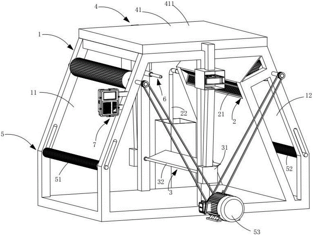
[0032] Such as figure 1 As shown, a negative pressure suction and drying device for textiles is characterized by comprising:

[0033] A box body 1, which includes a drying zone 11 on the left and a dust collection zone 12 on the right; and

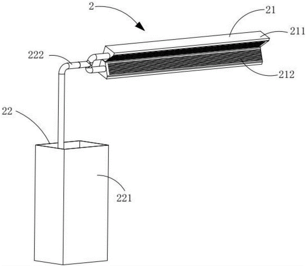
[0034] The negative pressure dust collection mechanism 2, which is arranged on the dust collection area 12, includes a dust collection assembly 21 and a dust collection assembly 22, and the dust collection assembly 22 communicates with the dust collection assembly 21;

[0035] A rotating and swinging mechanism 3, which is located at the front end of the dust suction mechanism 2, and is fixedly arranged on the drying area 11, and includes a rotating assembly 31 and a swinging assembly 32, the rotating assembly 31 works to drive the swinging assembly 32;

[0036] The drying mechanism 4 includes a ventilation assembly 41 arranged at the upper end of the drying zone 11 and a heating element 42 located directly below the ventilation assembly 41.

[0037]...

Embodiment approach

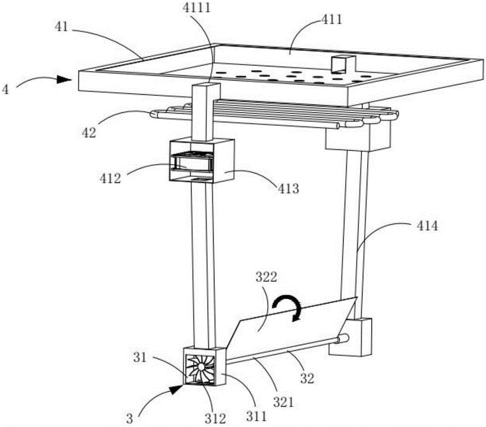
[0053] As a preferred embodiment, the exhaust assembly 41 includes:

[0054] A wind box 411, the wind box 411 is fixed at the upper end of the drying area 11, and the heating element 42 is arranged directly below the wind box 411; and

[0055] A plurality of fan cases 412, the fan case 412 is located at the upper end of the fan box 311, fixed symmetrically at the two ends of the drying area 11, and a fan 413 is horizontally disposed inside; and

[0056] The air duct 414 passes through the air box 412, one end of which is connected to the air box 411, and the other end is connected to the fan box 311.

[0057] It should be noted that the implementation of the ventilation assembly is not limited to the manner in the present invention. The fan 413 in the fan box 412 works to extract dry air outside the device. The air forms an airflow from the fan box 311 into the air duct 414. During the entry process, the fan wheel 312 is driven to rotate, and the fan wheel 312 drives the swing shaft 3...


PUM


Abstract

The invention discloses a textile negative pressure dust collection and drying device which comprises a negative pressure dust collection mechanism and a rotating and swing mechanism and furthermore comprises a drying mechanism; the negative pressure dust collection mechanism is arranged on a dust collection area and comprises a dust collection assembly and a dust gathering assembly; the rotating and swing mechanism is located at the front end of the dust collection mechanism and comprises a rotating assembly and a swing assembly; and the drying mechanism comprises an air pumping assembly arranged at the upper end of a drying area and a heating element located under the air pumping assembly. A textile is input into the drying area to be dried, in the drying process, the swing assembly swings all the time, and drying of the textile is accelerated while impurities on the textile fall off in the swing process through swing of the dried textile; and in addition, air flow formed in the swing process of the swing assembly flows to the dust collection mechanism, the dust collection mechanism is beneficial to absorption treatment of the impurities in a box body through air negative pressure formed both inside and outside the device, and thus quality of the textile is improved.

Description

Technical field [0001] The invention relates to the technical field of dust removal, in particular to a negative pressure suction and drying device for textiles. Background technique [0002] During the drying process of textiles, the textiles are easy to fall off some impurities such as fiber shavings, and most of the impurities will adhere to the textiles, which will seriously affect the quality of the textiles, and some of the debris remaining in the drying device Continuous accumulation, the drying device must be cleaned regularly, which brings inconvenience to the drying work. [0003] In the Chinese patent with the patent number CN 103743211 A, a dryer that can clean textile fabrics is mentioned. Although the impurities generated by the textile fabrics can be effectively removed by airflow, it only takes away the lower surface of the textile fabrics through the airflow. Impurities, and the impurities attached to the upper surface of the textile fabric, cannot penetrate the f...

Claims


Application Information

Patent Timeline
IPC IPC(8): F26B13/08F26B21/00F26B25/04B08B5/04
CPCB08B5/046F26B13/08F26B21/001F26B25/04
Inventor 臧伟
Owner 安徽舜发服装有限公司
Why Eureka
Try Eureka