Heat pipe core, heat pipe and sputtering process of heat pipe

A sputtering process and heat pipe technology, applied in the direction of tubular elements, indirect heat exchangers, heat exchange equipment, etc., can solve the problems of high heat conduction power loss ratio, low efficiency, large temperature difference between cold and hot ends, etc., and achieve detailed selection Specifications, increased heat conduction power, and reduced temperature difference

Inactive Publication Date: 2017-05-24
SUZHOU KANRONICS ELECTRONICS TECH CO LTD
View PDF12 Cites 6 Cited by
  • Summary
  • Abstract
  • Description
  • Claims
  • Application Information

AI Technical Summary

Problems solved by technology

[0002] The wick (liquid-absorbing wick) of the heat pipe is crucial to the performance of the heat pipe. The existing heat pipe (mesh wick) simply fills the tube with metal mesh. The finished heat pipe with this structure has a large temperature difference between the cold and hot ends, and the efficiency Technical issues such as relatively low ratio and high ratio of thermal conduction power loss

Method used


Image

  • Heat pipe core, heat pipe and sputtering process of heat pipe
  • Heat pipe core, heat pipe and sputtering process of heat pipe
  • Heat pipe core, heat pipe and sputtering process of heat pipe

Examples


Embodiment Construction

[0025] In order to understand the technical content of the present invention more clearly, the following examples are given in detail, the purpose of which is only to better understand the content of the present invention but not to limit the protection scope of the present invention. The components in the structures in the drawings of the embodiments are not scaled according to the normal scale, so they do not represent the actual relative sizes of the structures in the embodiments.

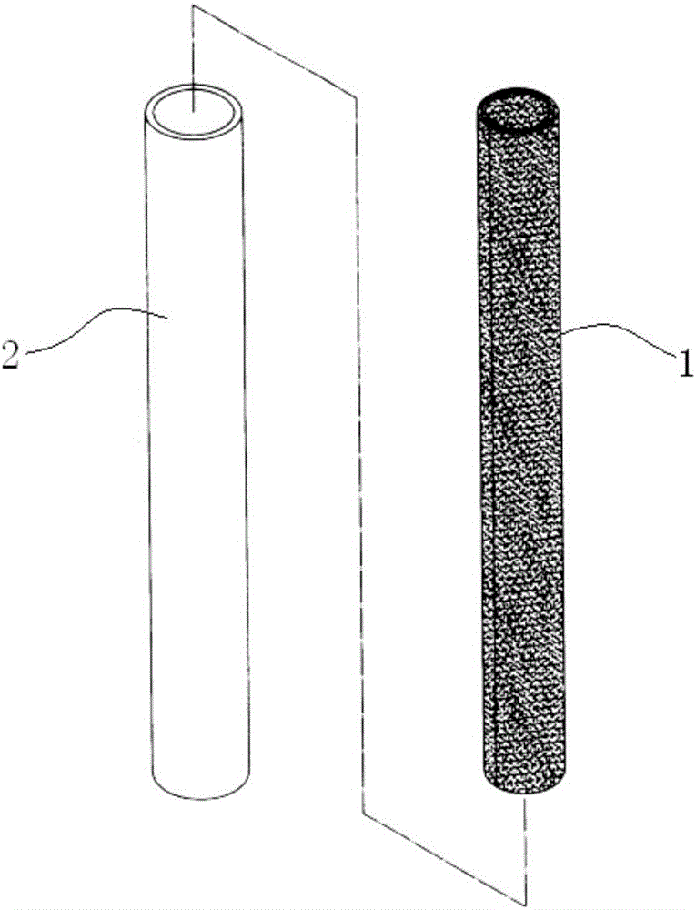
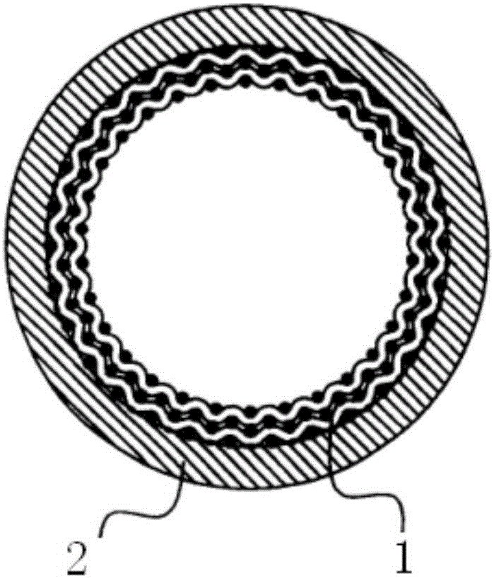
[0026] Such as figure 1 As shown, a heat pipe core 1 includes a single-layer, double-layer or more than two-layer sheet metal mesh, and the surface of the sheet metal mesh is sputtered with at least one layer of sputtering film made of graphene. When the sheet metal mesh and the sputtering film are installed on the inner wall of the metal shell of the heat pipe, they are in the shape of a circumferential butt joint pipe. In this way, a layer of graphene material is sputtered on the surface of t...


PUM

PropertyMeasurementUnit
thicknessaaaaaaaaaa
thicknessaaaaaaaaaa

Abstract

The invention discloses a heat pipe core, a heat pipe and a sputtering process of the heat pipe. The pipe core structure of a traditional heat pipe is improved. A layer of graphene material is arranged on the surface of a metal net attached to the inner wall of a metal pipe shell through sputtering. Due to the ultrahigh heat conductivity of graphene assisting traditional design, the response time in the heat pipe during phase change is promoted greatly, the efficiency of heat conduction is promoted, phase change switching time is shortened, thus the temperature difference of the cold end and the hot end of the heat pipe is reduced, and the heat conduction power is promoted. In addition, detailed quantitative processing is conducted on both the wire diameter and number of the metal net, and thus model selection specification of the heat pipe is detailed.

Description

technical field [0001] The invention relates to the technical field of heat conduction of heat pipes, in particular to a heat pipe core, a heat pipe and a sputtering process thereof. Background technique [0002] The wick (liquid-absorbing wick) of the heat pipe is crucial to the performance of the heat pipe. The existing heat pipe (mesh wick) simply fills the tube with metal mesh. The finished heat pipe with this structure has a large temperature difference between the cold and hot ends, and the efficiency Technical issues such as relatively low and high proportion of heat conduction power losses. Contents of the invention [0003] In order to solve the above technical problems, the present invention proposes a heat pipe core, a heat pipe and its sputtering process, which greatly improves the response time during the phase change process inside the heat pipe, improves the efficiency of heat conduction, and shortens the time for phase change conversion , so that the tempe...

Claims


Application Information

Patent Timeline
Patent Type & Authority Applications(China)
IPC IPC(8): F28D15/04F28F1/00
CPCF28D15/046F28F1/00
Inventor 郭志军王雷
Owner SUZHOU KANRONICS ELECTRONICS TECH CO LTD
Why Eureka
Try Eureka