Non-contact strain field and acoustic emission combined split type measuring system and method

A measurement system and measurement method technology, which are applied in material analysis using sonic emission technology, measurement device, material analysis using sonic/ultrasonic/infrasonic waves, etc. , affecting the load indication and other issues, to achieve the effect of less difficulty in experimental operation, low experimental test cost, and good fixation effect

Active Publication Date: 2017-05-24
NANJING UNIV OF AERONAUTICS & ASTRONAUTICS
View PDF14 Cites 2 Cited by
  • Summary
  • Abstract
  • Description
  • Claims
  • Application Information

AI Technical Summary

Problems solved by technology

[0004] Although many solutions for fixing acoustic emission sensors have been disclosed in the prior art, the prior art still cannot solve the problem of fixing the acoustic emission sensor during the joint test of the non-contact strain field and acoustic emission of non-magnetic materials. The main reasons are as follows: 1. Non-magnetic materials cannot use magnetic fixing method; 2. For frame fixing method, its structure is complicated
In the material mechanics experiment, the size of the test sample is generally small, so the experimental operation is difficult, and when used for the joint test of the non-contact strain field and acoustic emission, the fixture will produce a certain shielding on the surface of the test sample, resulting in the strain field measurement Unable to carry out; 3. Tape fixing method is a simple and easy method to fix the acoustic emission sensor, but in the same way, the tape will also block the test surface, so this solution cannot be used for the joint test of non-contact strain field and acoustic emission; 4 , The indirect fixation method pastes the conversion layer (plastic sleeve or metal plate) on the surface of the test sample, and then fixes the sensor through the conversion layer. The adhesive between the layer and the test sample will gradually debond, and the noise signal generated during the debonding process will affect the measurement results of acoustic emission
In addition, the transfer layer and the test sample will be jointly deformed by force during the experiment, which will affect the load indication to a certain extent, and will cause obvious deviations between the test results and the real results.

Method used


Image

  • Non-contact strain field and acoustic emission combined split type measuring system and method
  • Non-contact strain field and acoustic emission combined split type measuring system and method
  • Non-contact strain field and acoustic emission combined split type measuring system and method

Examples


Embodiment Construction

[0036] The present invention is described in further detail now in conjunction with accompanying drawing.

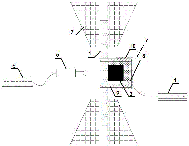
[0037] Such as figure 1As shown, the non-contact strain field and acoustic emission joint split measurement system includes a test sample 1, a testing machine fixture 2, an acoustic emission sensor 3, an acoustic emission acquisition system 4, a camera 5, an image acquisition control device 6, and a fixture 7. Test sample 1 is a rectangular strip-shaped non-magnetic material, such as a ceramic matrix composite material. The number of testing machine fixtures 2 is a pair, which are respectively clamped at the upper and lower ends of the test sample 1, and the test sample 1 is tested by the testing machine. stretch. The acoustic emission sensor 3 and the camera 5 are respectively fixed on the left and right opposite sides of the test sample 1, the acoustic emission sensor 3 sends the collected acoustic signal to the acoustic emission collection system 4, and the camera 5 ...


PUM

PropertyMeasurementUnit
lengthaaaaaaaaaa
thicknessaaaaaaaaaa

Abstract

The invention discloses a non-contact strain field and acoustic emission combined split type measuring system and method. The system comprises a testing sample, two testing machine clamps, an acoustic emission sensor, an acoustic emission acquisition system, a camera, image acquisition control equipment and a fixing device, wherein the testing sample adopts a rectangular strip nonmagnetic material; the two testing machine clamps respectively clamp the upper and lower ends of the testing sample and stretch the testing sample; the acoustic emission sensor and the camera are respectively fixed on the left and right opposite sides of the testing sample; the acoustic emission sensor sends collected acoustic signals to the acoustic emission acquisition system; the camera sends collected image signal to the image acquisition control equipment; the acoustic emission sensor adopts a cylinder; a sensing surface is formed on the top surface of the cylinder; the acoustic emission sensor is fixed through the fixing device, so as to ensure that the sensing surface of the acoustic emission sensor is adhered to the surface of the testing sample. The system is simple in structure, and high in reliability and testing precision, and can effectively solve the problem in fixing the nonmagnetic material.

Description

technical field [0001] The invention belongs to the technical field of non-destructive testing, and in particular relates to a non-contact strain field and acoustic emission combined split measurement system and method. Background technique [0002] Non-destructive testing technology can monitor the defect distribution and damage development of the research object without damaging the material. For example, the measurement of the non-contact strain field can study the full-field deformation characteristics of the material during the stress process, and the test device can keep a certain distance from the test sample. The acoustic emission testing technology can monitor the damage development of the material online in real time to obtain the micro Crack initiation and propagation information, and damage localization. The combination of non-contact strain field testing technology and acoustic emission testing technology can effectively study the relationship between the damag...

Claims


Application Information

Patent Timeline
Patent Type & Authority Applications(China)
IPC IPC(8): G01N29/14G01N29/22G01N3/36G01B11/16
CPCG01B11/16G01N3/36G01N29/14G01N29/223G01N2203/0007G01N2203/0017G01N2203/0048G01N2203/0682G01N2291/0232G01N2291/0289G01N2291/101G01N2291/263
Inventor 宋迎东于国强高希光谢楚阳杨丛橙
Owner NANJING UNIV OF AERONAUTICS & ASTRONAUTICS
Why Eureka
Try Eureka