Display panel, display device and driving method

A display panel and substrate technology, applied in static indicators, instruments, optics, etc., can solve the problem of not being able to take into account the thickness of the luminous efficiency liquid crystal box, so as to improve the utilization rate of light energy and luminous efficiency, and take into account the thickness of the liquid crystal box, less The effect of light energy loss

Inactive Publication Date: 2017-05-24
BOE TECH GRP CO LTD
View PDF4 Cites 45 Cited by
  • Summary
  • Abstract
  • Description
  • Claims
  • Application Information

AI Technical Summary

Problems solved by technology

[0004] The present invention aims at the above-mentioned deficiencies in the prior art, and provides a display panel, a display device and a driving method to at least partly solve the problem of not being able to balance the luminous efficiency and the thickness of the liquid crystal cell

Method used


Image

  • Display panel, display device and driving method
  • Display panel, display device and driving method
  • Display panel, display device and driving method

Examples


Embodiment 1

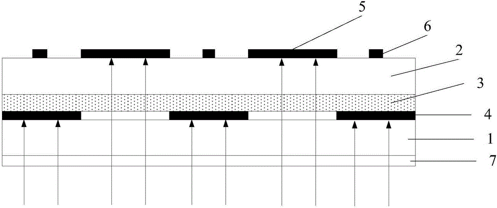
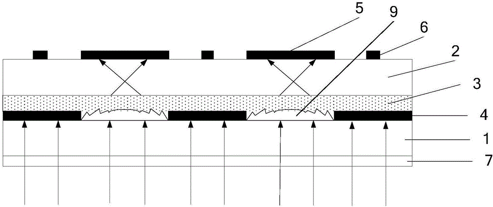
[0046] Such as Figure 1a and Figure 1b As shown, Embodiment 1 of the present invention provides a display panel, Figure 1a A schematic diagram of the optical path of the display panel provided in Example 1 at L0, Figure 1b A schematic diagram of the optical path of the display panel provided in Example 1 at L255.

[0047] The display panel includes a first substrate 1, a second substrate 2, and a liquid crystal layer 3 disposed between the first substrate 1 and the second substrate 2, wherein the first substrate 1 may be an array substrate, and the second substrate 2 may be Color film substrate. A first black matrix 4 is disposed on a side of the first substrate 1 adjacent to the liquid crystal layer 3 , that is, the first black matrix 4 is disposed on the light emitting side of the first substrate 1 . A second black matrix 5 is disposed on a side of the second substrate 2 away from the liquid crystal layer 3 , that is, the second black matrix 5 is disposed on the light ...

Embodiment 2

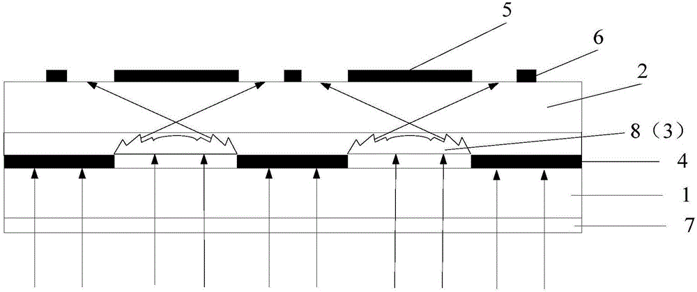
[0074] Such as Figure 2a and Figure 2b As shown, Embodiment 2 of the present invention provides a display panel, Figure 2a A schematic diagram of the optical path of the display panel provided in Example 2 at L0, Figure 2b Schematic diagram of the optical path of the display panel at L255 provided for Example 2.

[0075] The difference between embodiment 2 and embodiment 1 is that the composition and structure of the optical device are different. The optical device of embodiment 1 is a liquid crystal Fresnel lens, while the optical device of embodiment 2 is composed of a solid Fresnel lens and a liquid crystal lens combination lens. Other structures of the display panel provided in Embodiment 2 are the same as those of the display panel provided in Embodiment 1, and will not be repeated here.

[0076] The following combination Figure 2a and Figure 2b , the optical device of Example 2 will be described in detail.

[0077] Such as Figure 2b As shown, the optical d...

Embodiment 3

[0088] Embodiment 3 of the present invention provides a display device, which includes the display panel as described in Embodiment 1 or 2.

[0089] By arranging the first black matrix 4 on the light emitting side of the array substrate (i.e. the first substrate 1), and arranging the second black matrix 5 on the light emitting side of the color filter substrate (i.e. the second substrate 2), the first black matrix 4 and the second black matrix 4 are arranged. Two black matrixes 5 are arranged at intervals, and by arranging at least part of the optical device in the liquid crystal layer 3, when there is a voltage difference between the two sides of the liquid crystal layer 3, the optical device can change the outgoing direction of the outgoing light and expand the outgoing angle of the incident light , namely to refract the incident light, and make the refracted incident light exit from between adjacent second black matrices 5 . In this way, the gray scale change of the display...


PUM


Abstract

The invention provides a display panel, a display device and a driving method. A first black matrix is arranged on a light outgoing side of an array substrate, a second black matrix is arranged on a light outgoing side of a colored film substrate, the first black matrix and the second black matrix are arranged at an interval, and an optical device partly positioned in a liquid crystal layer at least is arranged; when two sides of the liquid crystal layer have a voltage difference, the optical device can emergent direction of emergent light and expand emergent angle of incident light, in this way, the voltage difference on the two sides of the liquid crystal layer can be controlled, and gray scale change of the display panel and the display device can be controlled; on one side, a polaroid does not need to be arranged on the outer side of the colored film substrate, so that light energy utilization rate and light emitting efficiency are improved; on the other side, the optical device can realize effect of a liquid crystal lens partly at least, so that thickness of a liquid crystal box is reduced to certain extent, and the light emitting efficiency and the thickness of the liquid crystal box are taken into consideration at the same time.

Description

technical field [0001] The present invention relates to the field of display technology, in particular to a display panel, a display device and a driving method. Background technique [0002] The current LCD (Liquid Crystal Display, liquid crystal display) includes a backlight source, an array substrate and a color filter substrate, a liquid crystal layer is arranged between the array substrate and the color filter substrate, a thin film transistor array is arranged on the array substrate, and each thin film transistor corresponds to a Pixels and color filter substrates are equipped with color filters of corresponding colors at positions corresponding to sub-pixels. By controlling the signals and voltages on each thin film transistor, the rotation direction of liquid crystal molecules is controlled, thereby controlling the emission of polarized light from each pixel. for display purposes. Polarizers are arranged on the outer sides of the array substrate and the color filter...

Claims


Application Information

Patent Timeline
Patent Type & Authority Applications(China)
IPC IPC(8): G02F1/1335G02F1/133
CPCG02F1/13306G02F1/133512G02F1/133514G02B5/003G02F1/29G02F1/133565G02F1/291G02B3/12G02F1/133526G02F1/19
Inventor 朱劲野赵文卿王海燕
Owner BOE TECH GRP CO LTD
Why Eureka
Try Eureka