Optical imaging lens and imaging equipment

An optical imaging lens and imaging surface technology, applied in the field of imaging lenses, can solve the problems of the difficulty of pixel point size of the photosensitive chip, the inability to meet the needs of use, and the difficulty of correcting lens edge aberrations, so as to increase the imaging range, improve the Thermal stability as well as the effect of mechanical strength, good image quality

Active Publication Date: 2021-04-09
合肥联创光学有限公司
View PDF1 Cites 1 Cited by
  • Summary
  • Abstract
  • Description
  • Claims
  • Application Information

AI Technical Summary

Problems solved by technology

[0003] According to the current technology, it is more and more difficult to reduce the pixel size of the photosensitive chip. Therefore, in order to pursue more pixels, the size of the chip is getting larger and larger, which means that the lens needs to have a larger imaging range. In this case, the requirements for the resolution of the lens are getting higher and higher, and the edge aberration of the lens is difficult to correct, and the edge imaging effect is poor, which cannot well meet the needs of vehicles, surveillance, sports cameras and other fields.

Method used


Image

  • Optical imaging lens and imaging equipment
  • Optical imaging lens and imaging equipment
  • Optical imaging lens and imaging equipment

Examples


no. 1 example

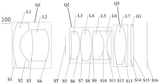
[0064] see figure 1 , is a schematic structural diagram of the optical imaging lens 100 provided in the first embodiment of the present invention, the optical imaging lens 100 includes in sequence from the object side to the imaging surface along the optical axis: a first group Q1, a diaphragm ST, and a second group Q2 , the third group Q3, the filter G1.

[0065] The first group Q1 includes a first lens L1 and a second lens L2.

[0066] The first lens L1 has negative refractive power, the object side S1 of the first lens is convex, the image side S2 of the first lens is concave, and the first lens L1 is a glass spherical lens.

[0067] The second lens L2 has positive refractive power, the object side S3 of the second lens is concave, the image side S4 of the second lens is convex, and the second lens L2 is a glass aspherical lens.

[0068] The second group Q2 includes a third lens L3, a fourth lens L4, a fifth lens L5, and a sixth lens L6.

[0069] The third lens L3 has po...

no. 2 example

[0086] see Figure 4 , is a schematic structural diagram of the optical imaging lens 200 provided by the second embodiment of the present invention. The optical imaging lens 200 in this embodiment is roughly the same as the optical imaging lens 100 in the first embodiment, the difference is that the object side surface S3 of the second lens L2 of the optical imaging lens 200 in this embodiment is a convex surface, and the second lens L2 of the optical imaging lens 200 in this embodiment is convex. The image side S10 of the fifth lens L5 is a concave surface, and the object side S10 of the sixth lens L6 is a convex surface, and the radius of curvature and material selection of each lens are different. The relevant parameters of each lens are shown in Table 3.

[0087] table 3

[0088]

[0089] The parameters of each lens aspheric surface in this embodiment are shown in Table 4.

[0090] Table 4

[0091]

[0092] In this embodiment, the graphs of the distortion and the ...

no. 3 example

[0096] see Figure 7 , shows a structural diagram of the optical imaging lens 300 provided by the second embodiment of the present invention. The optical imaging lens 300 in this embodiment is roughly the same as the optical imaging lens 100 in the first embodiment, the difference is that the object side surface S5 of the third lens L3 of the optical imaging lens 300 in this embodiment is a convex surface, and The radius of curvature and material selection of each lens are different, and the relevant parameters of each lens are shown in Table 5.

[0097] table 5

[0098]

[0099] The parameters of each lens aspheric surface in this embodiment are shown in Table 6.

[0100] Table 6

[0101]

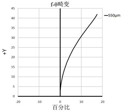
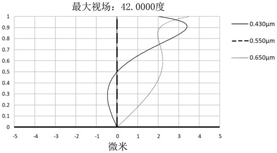
[0102] In this embodiment, the graphs of the distortion and the vertical axis chromatic aberration of the optical imaging lens 300 are as follows Figure 8 and Figure 9 shown.

[0103] Depend on Figure 8 It can be seen that the f-θ distortion of the optical imaging lens 300 ...


PUM


Abstract

The invention discloses an optical imaging lens and imaging equipment, wherein the optical imaging lens sequentially comprises a first group with a negative focal power,a diaphragm, a second group with a positive focal power, a third group with a positive focal powerand a light filter from an object side to an imaging surface along an optical axis; the first group comprises a first lens with negative focal power and a second lens with positive focal power, the object side surface of the first lens is convex surface,the image side surface of the first lens is concave surface, and the image side surface of the second lens is convex surface; the second group comprises a third lens with positive focal power, a fourth lens with positive focal power, a fifth lens with positive focal power, and a sixth lens with negative focal power, the object side surface and the image side surface of the fourth lens are convex surfaces, the object side surface of the fifth lens is convex surface, and the image side surface of the sixth lens is concave surface; the fifth lens and the sixth lens form a bonding body; the third group comprises a seventh lens with positive focal power, and the object side surface and the image side surface of the seventh lens are convex surfaces. The optical imaging lens at least has the advantages of high pixel and small distortion, and has a temperature compensation effect.

Description

technical field [0001] The invention relates to the technical field of imaging lenses, in particular to an optical imaging lens and imaging equipment. Background technique [0002] With the continuous development of vehicle, monitoring, sports cameras and other fields, the requirements for the pixel and stability of the lens are getting higher and higher. [0003] According to the current technology, it is more and more difficult to reduce the pixel size of the photosensitive chip. Therefore, in order to pursue more pixels, the size of the chip is getting larger and larger, which means that the lens needs to have a larger imaging range. In this case, the requirements for the resolution of the lens are getting higher and higher, and the edge aberration of the lens is difficult to correct, and the edge imaging effect is poor, which cannot well meet the needs of the fields of vehicle, surveillance, and sports cameras. Contents of the invention [0004] Therefore, the object ...

Claims


Application Information

Patent Timeline
Patent Type & Authority Applications(China)
IPC IPC(8): G02B13/00G02B13/18G02B1/00G02B7/02G03B30/00
CPCG02B1/00G02B7/028G02B13/00G02B13/18
Inventor 魏文哲王克民曾吉勇
Owner 合肥联创光学有限公司
Why Eureka
Try Eureka