Design method of no-commutating permanent magnet direct current rotating motor
A rotating motor, permanent magnet DC technology, applied in the direction of magnetic circuit rotating parts, magnetic circuit, electric components, etc., can solve the problems of low failure rate and long service life
- Summary
- Abstract
- Description
- Claims
- Application Information
AI Technical Summary
Problems solved by technology
Method used
Image

Examples
Embodiment 1
[0025] Example 1: Design scheme of single-stator non-commutating permanent magnet DC rotary motor
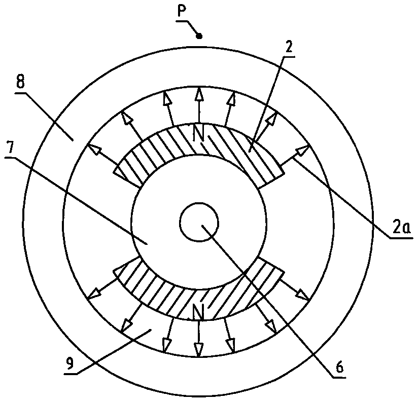
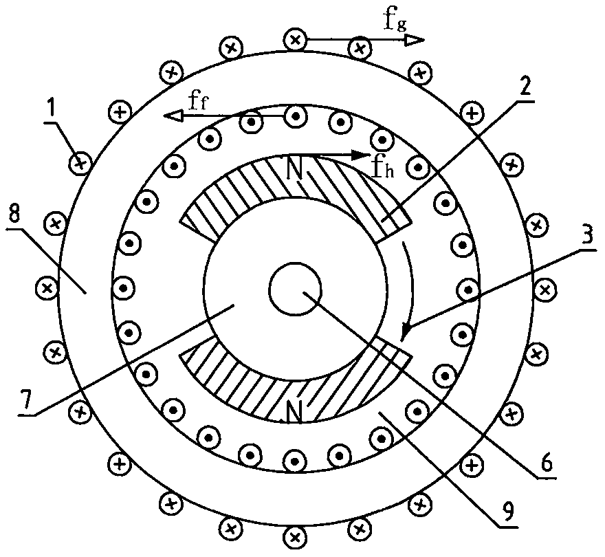
[0026] Figure 4 (a) represents the design scheme of a single-stator non-commutating permanent magnet DC rotary generator; Figure 4(b) represents the design scheme of a single-stator non-commutated permanent magnet DC rotating motor. The structural forms of the two schemes are the same, mainly composed of a stator and a rotor. The rotor part: consists of a rotating shaft 6, a rotor ferromagnetic set 7 and a tile-shaped permanent magnet 2; the stator part: consists of a ferromagnetic stator core 8a, a non-magnetic The ferromagnetic stator core 8b and the DC winding 1 are composed. An air gap 9 is provided between the rotor and the stator. The ferromagnetic stator core 8a is in the shape of a cylinder, and the inner side is provided with a notch for winding the coil; the non-ferromagnetic stator core 8b is also in the shape of a ring, and the outer side is provided with a notc...
Embodiment 2
[0031] Example 2: Design scheme of double-pole, double-stator non-commutating permanent magnet DC rotary motor
[0032] see Figure 5 , wherein the structures of the two stators are exactly the same, only a ferromagnetic magnetic circuit 8c and a positioning block 10 need to be set between the two stators. Figure (a) is a cross-sectional view along the axial direction, Figure (b) is a cross-sectional view along the A-A direction, and Figure (c) is a cross-sectional view along the B-B direction. The permanent magnetic circuit path of this scheme: N pole of the right permanent magnet → rotor ferromagnetic set 7 → S pole of the left permanent magnet → N pole of the left permanent magnet → air gap 9 → left stator core 8a → iron Magnetic magnetic circuit 8c→right stator core 8a→air gap 9→right permanent magnet S pole. The working principle is exactly the same as Example 1. Since the permanent magnet magnetic circuit of this scheme is complete and no flux leakage will occur, it i...
Embodiment 3
[0033] Embodiment 3: Design scheme of permanent magnet direct current rotary motor without commutation of outer rotor
[0034] see Figure 6 , and example 1 and example 2 are different: this design scheme is that permanent magnet 2 is installed on the outer rotor ferromagnetic casing 7, and cylindrical iron core and coil are stator. 11 among the figure represents inner stator fixing plate. Because there is a non-ferromagnetic medium in the permanent magnet magnetic circuit, there is flux leakage in this scheme, so it is more suitable for designing and manufacturing a small outer rotor non-commutating permanent magnet DC rotating motor.
[0035] The manufacturing process and winding method of the stator core:
[0036] Such as Figure 7 As shown, the design method of the non-commutated permanent magnet DC rotating machine of the present invention, the stator core is an assembly. The design should take into account the convenience of the stator coil 1 winding process. Figur...
PUM
 Abstract
Description
Claims
Application Information
 - R&D
- Intellectual Property
- Life Sciences
- Materials
- Tech Scout
- Unparalleled Data Quality
- Higher Quality Content
- 60% Fewer Hallucinations
Browse by: Latest US Patents, China's latest patents, Technical Efficacy Thesaurus, Application Domain, Technology Topic, Popular Technical Reports.
© 2025 PatSnap. All rights reserved.Legal|Privacy policy|Modern Slavery Act Transparency Statement|Sitemap|About US| Contact US: help@patsnap.com