Vacuum filtering device

A filter device and vacuum technology, applied in the direction of filtration separation, gravity filter, fixed filter element filter, etc., can solve the problems of difficult cleaning, non-replacement, high cost, etc., and achieve the effect of easy cleaning, convenient fixing, and low surface tension

Pending Publication Date: 2017-05-31
SHANGHAI ANPEL SCI INSTR
View PDF0 Cites 6 Cited by
  • Summary
  • Abstract
  • Description
  • Claims
  • Application Information

AI Technical Summary

Problems solved by technology

[0003] 1. The device is made of glass material, which is easy to break;
[0004] 2. The sand core is usually quartz sand, which is easy to break, cannot be replaced, and is difficult to clean. When different solvents need to be filtered, in order to avoid cross-contamination, multiple sets of devices need to be prepared, which is costly;

Method used


Image

  • Vacuum filtering device

Examples


Embodiment 1

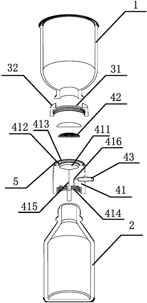
[0032] figure 1 Schematically provides a simplified structural diagram of the vacuum filter device of the present embodiment, as figure 1 As shown, the vacuum filter device includes: a filter cup 1, a filtrate bottle 2, and the vacuum filter device further includes:

[0033] A snap ring, the snap ring includes a ring 31 and a snap ring arm 32, the ring has a first internal thread, and the snap ring is connected to the filter main body through the first internal thread; the snap ring arm has at least two , for buckling and fixing the filter cup;

[0034] A filter subject, the filter subject comprising:

[0035] Body 41, the body is made of polytetrafluoroethylene; the upper bottom surface of the body is provided with a first groove 411, and a first blocking portion 412 is provided in the first groove; the upper side of the body A first external thread matching the first internal thread is provided; a second groove 414 is provided on the lower bottom surface of the body, and ...

Embodiment 2

[0049] This embodiment provides a vacuum filtration device according to Embodiment 1 of the present invention. In this embodiment, the first groove includes three parts, which are respectively an inverted cone part, a filter membrane support part and a sealing ring from bottom to top. The blocking part, the filter membrane supporting part and the sealing ring blocking part are cylindrical, and the bottom surface radius of the sealing ring part blocking part is larger than the bottom surface radius of the filter membrane supporting part and larger than the bottom surface radius of the inverted conical part, forming a second step surface, and the two-stage stepped surface constitutes the second blocking portion and the first blocking portion.


PUM


Abstract

The invention relates to a vacuum filtering device. The vacuum filtering device comprises a filtering cup and a filtrate bottle, and further comprises a clamp ring and a filtering main body, wherein the clamp ring comprises a circular ring and clamp ring arms and is used for fixing the filtering main body and the filtering cup; the filtering main body comprises a body, a filtering film supporting member and a filtration joint; the upper bottom surface of the body is provided with a first groove; the interior of the first groove is provided with a first blocking part; the upper part of the side surface of the body is provided with a first outer screw thread matching with a first inner screw thread; the lower bottom surface of the body is provided with a second groove which is connected with the filtrate bottle; the interior of the body is also provided with a filtrate channel and a gas channel; the first groove communicates with the second groove through the filtrate channel; the second groove communicates with the exterior of the filtering main body through the gas channel; the filtering film supporting member is arranged on the first blocking part; and the filtration joint is arranged on the gas channel and extends out of the body. The vacuum filtering device provided by the invention has the advantages of simple structure, firmness, durability, use convenience, cleaning easiness, etc.

Description

technical field [0001] The invention relates to the field of solvent filtration, in particular to a vacuum filter device whose filter body adopts polytetrafluoroethylene material. Background technique [0002] In experiments such as liquid chromatography analysis, gravimetric analysis, microanalysis, separation and purification, vacuum filtration devices are often used to quickly filter and degas the solution. At present, the vacuum filtration devices commonly used in laboratories are made of glass, including glass filter cups, sand core filter heads, triangular liquid collection bottles and metal clips, but there are the following problems: [0003] 1. The device is made of glass material, which is easy to break; [0004] 2. The sand core is usually quartz sand, which is easy to break, cannot be replaced, and is difficult to clean. When different solvents need to be filtered, in order to avoid cross-contamination, multiple sets of devices need to be prepared, which is cost...

Claims


Application Information

Patent Timeline
IPC IPC(8): B01D29/085
CPCB01D29/085
Inventor 宋炜张佳孙佳麒
Owner SHANGHAI ANPEL SCI INSTR
Why Eureka
Try Eureka