
Waste gas treatment device for power station

A technology for waste gas treatment devices and power plants, which is applied in the direction of combined devices, separation of dispersed particles, chemical instruments and methods, etc., and can solve problems such as inability to remove dust and poor waste gas treatment effect

Inactive Publication Date: 2017-05-31
TIANJIN FANGYUAN ELECTRIC EQUIP
View PDF0 Cites 5 Cited by
  • Summary
  • Abstract
  • Description
  • Claims
  • Application Information

AI Technical Summary

Problems solved by technology

[0004] The purpose of the present invention is to provide an exhaust gas treatment device for a power plant, aiming to solve the problems in the prior art that the exhaust gas treatment effect is poor and dust cannot be removed

Method used


Image

  • Waste gas treatment device for power station

Examples


Embodiment Construction

[0012] The invention provides a waste gas treatment device of a power plant. The invention has the advantages of simple structure, convenient use, strong dust removal ability, low operation cost and good waste gas treatment effect.

[0013] The technical solutions in the embodiments of the present invention will be described clearly and in detail below in conjunction with the accompanying drawings in the embodiments of the present invention. Obviously, the described embodiments are only part of the embodiments of the present invention, not all of them. Based on the embodiments of the present invention, all other embodiments obtained by persons of ordinary skill in the art without making creative efforts belong to the protection scope of the present invention.

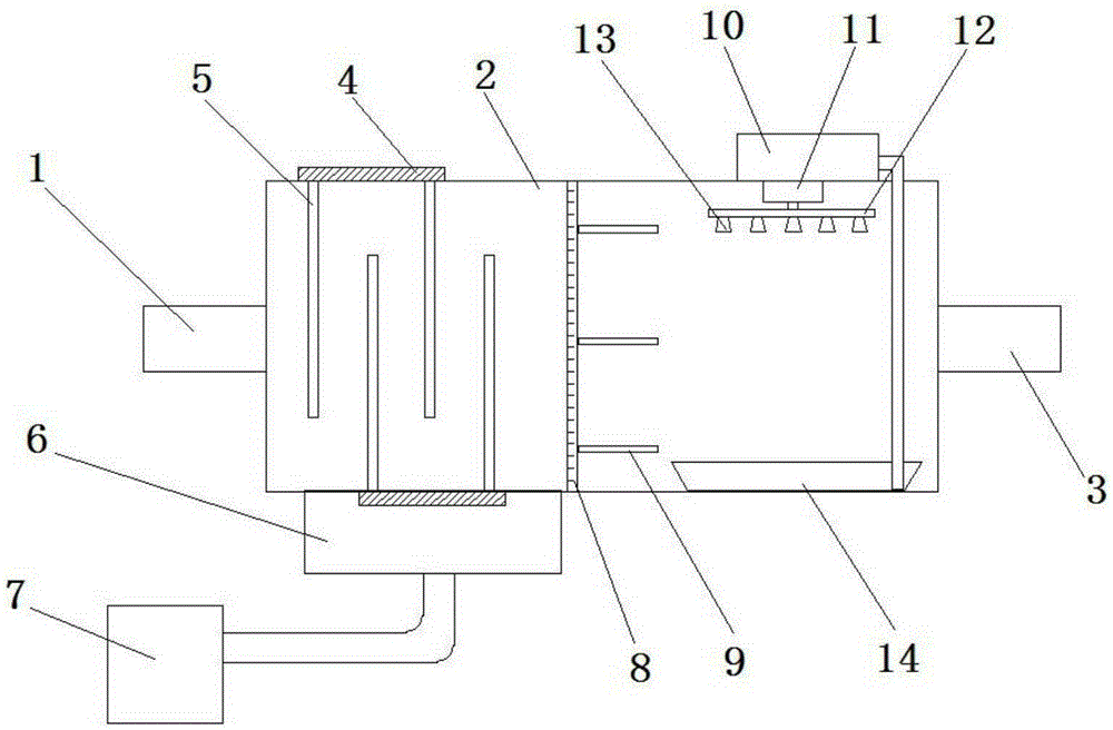
[0014] Such as figure 1 The exhaust gas treatment device of the power plant shown includes intake pipe 1, box body 2, exhaust pipe 3, fixed plate 4, baffle plate 5, collection box 6, dust removal box 7, filter screen 8,...


PUM


Abstract

The invention discloses a waste gas treatment device for a power station. One end of a box body is connected with a gas inlet pipe; the other end of the box body is connected with a gas exhaust pipe; a fixed plate is arranged on the external side, close to one end of the gas inlet pipe, of the box body; a baffle is perpendicular to the fixed plate; the baffle extends into the box body; the baffle can be pulled out by the fixed plate; a collecting box is arranged at the lower end of the fixed plate; the collecting box is connected with a dust cleaning box through a pipeline; a filter screen is arranged on the right side of the baffle; a plurality of air guide plates are uniformly arranged on the right side of the filter screen; a circulating pump is arranged on the external side of the top end of the box body on the right sides of the air guide plates; a motor is arranged at the top end of the internal side of the box body; the lower end of an output shaft of the motor is connected with a dispersion pipe; a plurality of atomizing nozzles are arranged at the lower end of the dispersion pipe; the circulating pump is connected with the dispersion pipe; a collecting pond is arranged right under the dispersion pipe; and one end of a pipeline extends to the bottom of the collecting pond, and and the other end of the pipeline is connected with the circulating pump. The waste gas treatment device for the power station, disclosed by the invention, has the advantages of simple structure, convenient use, strong dust cleaning capacity, low operation cost and good waste gas treatment effect.

Description

technical field [0001] The invention relates to the technical field of power plant equipment, and more specifically, relates to an exhaust gas treatment device of a power plant. Background technique [0002] Thermal power generation is a power generation method in which the thermal energy generated during the combustion of solid, liquid, and gaseous fuels such as coal, oil, and natural gas is converted into electrical energy through a power generation device, but the SO emitted by direct combustion of coal 2 , NOx and other acid gases continue to increase, which increases the amount of acid rain in many areas of China. The country produces 1.4 million tons of SO every year 2 , Traditional exhaust gas treatment devices generally only do simple treatment of exhaust gas, that is, discharge it outdoors, and the treatment efficiency is unstable, and it is easy to be affected by the outdoor environment and cause large fluctuations. Moreover, in the existing waste gas treatment e...

Claims


Application Information

Patent Timeline
IPC IPC(8): B01D50/00B01D53/78B01D53/60
Inventor 郝晨
Owner TIANJIN FANGYUAN ELECTRIC EQUIP
Learn More