Feed raw material micro-grinding system

A feed material and micro-grinding technology, which is applied in feed, grain processing, food science, etc., can solve the problems of increasing the difficulty of granulation, increasing equipment cost, increasing equipment load, etc., to avoid poor grinding effect and dust leakage , The effect of purifying the production environment

Active Publication Date: 2021-01-05
云南龙谷生物科技有限公司
View PDF7 Cites 0 Cited by
  • Summary
  • Abstract
  • Description
  • Claims
  • Application Information

AI Technical Summary

Problems solved by technology

[0002] Feed is composed of feed raw materials after crushing and granulation. In the process of feed crushing, if the crushed particles are large, on the one hand, it will increase the difficulty of pelleting, on the other hand, it will affect the digestion and absorption of feed by animals, resulting in huge waste of
Therefore, in the prior art, the scheme that can finely pulverize the feed has been sought, the existing system for feed pulverization is to directly set the rotating shaft in the pulverizing cylinder, and the pulverizing blade is arranged on the rotating shaft, but there is a huge disadvantage in this way. problem, resulting in poor shredding
For example: straw is widely used in feed processing as an important raw material, but due to its special shape, if the straw is directly crushed without crushing and cutting first, the load on the equipment will be greatly increased and the service life of the equipment will be affected
At the same time, in the prior art, after crushing, the raw materials after crushing are usually separated by screens. The qualified products enter the next process, and the unqualified products are sent back through the return pipe to be crushed again. The addition of equipment for returning materials on the pipe increases the cost of the equipment, on the other hand it also prolongs the crushing time, and at the same time it is not convenient for the collection and transfer of materials

Method used


Image

  • Feed raw material micro-grinding system
  • Feed raw material micro-grinding system
  • Feed raw material micro-grinding system

Examples


Embodiment Construction

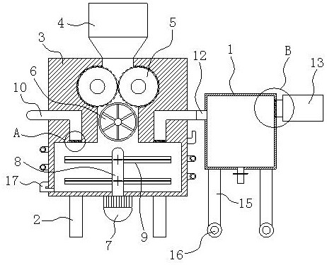
[0014] to combine Figure 1-4 A feed raw material micro-grinding system shown includes a pulverizer and a material transfer box 1 located on one side of the pulverizer. The pulverizer includes a support leg 2 and a main body 3 arranged on the support leg 2. The main body 3 The top is provided with a hopper 4, and the upper part of the main body 3 is provided with a reverse-shaped coarse crushing cavity, and the feed raw materials are initially crushed in the coarse crushing cavity. The top of the coarse crushing chamber communicates with the feed hopper 4, and the lower part of the main body 3 is provided with a fine crushing chamber connected to the bottom of the coarse crushing chamber, and the preliminarily crushed feed material is crushed again in the fine crushing chamber.

[0015] Two parallel rolling rollers 5 are arranged on the upper part of the coarse crushing chamber, and breaking rollers 6 are arranged on the lower part. The rolling roller 5 is used to crush the r...


PUM


Abstract

The invention relates to the technical field of feed machining and aims to provide a feed raw material fine smashing system which is high in smashing efficiency and facilitates transferring of materials. According to the technical scheme, the feed raw material fine smashing system comprises a smashing machine and a material transferring box located on one side of the smashing machine. The smashing machine comprises supporting legs and a body. The top of the body is provided with a feeding hopper. A rough smashing cavity is arranged on the upper portion in the body. A fine smashing cavity is arranged on the lower portion in the body. Grinding rollers are arranged on the upper portion of the rough smashing cavity. A breaking roller is arranged on the lower portion of the rough smashing cavity. Material suction pipes are arranged inside the body and located on the two sides of the rough smashing cavity. One end of each material suction pipe communicates with the top of the fine smashing cavity. A first filtering screen network is arranged at the end, communicating with the top of the fine smashing cavity of each material suction pipe. The feed raw material fine smashing system grinds and cuts raw materials firstly and then smashes the raw materials, so that the smashing effect is improved, it can be avoided that coarse materials are accumulated at the bottom of the fine smashing cavity, the smashing efficiency is higher, and material transferring is facilitated.

Description

technical field [0001] The invention relates to the technical field of feed processing, in particular to a feed raw material micro-grinding system. Background technique [0002] Feed is composed of feed raw materials after crushing and granulation. In the process of feed crushing, if the crushed particles are large, on the one hand, it will increase the difficulty of pelleting, on the other hand, it will affect the digestion and absorption of feed by animals, resulting in huge waste. Therefore, in the prior art, the scheme that can finely pulverize the feed has been sought, the existing system for feed pulverization is to directly set the rotating shaft in the pulverizing cylinder, and the pulverizing blade is arranged on the rotating shaft, but there is a huge disadvantage in this way. problem, resulting in poor shredding results. For example: straw is widely used in feed processing as an important raw material, but due to its special shape, if the straw is directly crush...

Claims


Application Information

Patent Timeline
Patent Type & Authority Patents(China)
IPC IPC(8): B02C21/00B02C4/08B02C18/12B02C23/20B02C18/18B02C13/06A23N17/00
CPCA23N17/00B02C4/08B02C13/06B02C18/12B02C18/186B02C21/00B02C23/20
Inventor 严存兵
Owner 云南龙谷生物科技有限公司
Why Eureka
Try Eureka