Hot air protection device for wet-type electrostatic precipitator

A wet electrostatic precipitator and protection device technology, applied in the direction of external electrostatic separator, electrostatic separation, etc., can solve the problems of high power consumption of electric heaters, pollution of heat preservation barrels, large selection of fans, etc., to ensure stable operation, reduce Power consumption, avoid the effect of flue gas back-channeling

Active Publication Date: 2017-05-31
CHINA HUADIAN ENG +1
View PDF6 Cites 0 Cited by
  • Summary
  • Abstract
  • Description
  • Claims
  • Application Information

AI Technical Summary

Problems solved by technology

The main problems in the existing system are that the selection of the fan is too large, the power consumption of the electric hea

Method used


Image

  • Hot air protection device for wet-type electrostatic precipitator
  • Hot air protection device for wet-type electrostatic precipitator

Examples


Example Embodiment

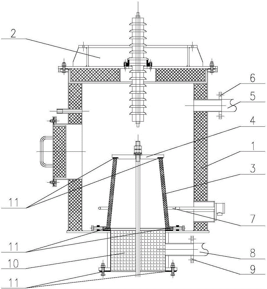
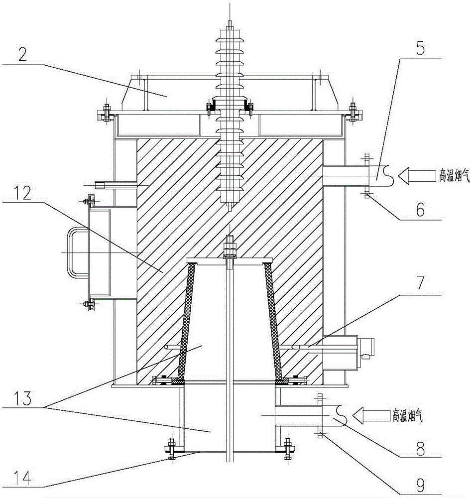
[0019] Embodiment 1 of the present invention: such as figure 1 with figure 2 As shown, a hot air protection device suitable for a wet dust collector of a 300MMW thermal power generating unit includes a heat preservation barrel body 1, a heat preservation barrel top cover 2, an insulator body 3, an insulator cover plate 4, an outer protection system and an inner protection system 7. A seal 11 is installed between the insulator body 3 and the insulator cover plate 4 for sealing treatment. The external protection system is arranged on the outside of the heat preservation barrel body 1, and the lower part of the heat preservation barrel body 1 is also provided with a heat preservation barrel connection block 10, and the inner diameter of the heat preservation barrel connection block 10 is 430 mm. The inner wall of the heat preservation bucket body 1, the top cover 2 of the heat preservation bucket and the outer wall of the insulator body 3 form a heat preservation bucket inner cha...

Example Embodiment

[0021] Example 2: Such as figure 1 with figure 2 As shown, the hot air protection device for a wet electric precipitator includes a heat preservation barrel body 1, a heat preservation barrel top cover 2, an insulator body 3, an insulator cover plate 4, an outer protection system and an inner protection system 7. The external protection system is arranged outside the heat preservation barrel body 1, and a heat preservation barrel connection block 10 is also arranged at the lower part of the heat preservation barrel body 1. The inner wall of the heat preservation bucket body 1, the top cover 2 of the heat preservation bucket and the outer wall of the insulator body 3 form a heat preservation bucket inner chamber 12. The inner wall of the insulator body 3, the insulator cover 4 and the inner wall of the insulating barrel connecting block 10 form a insulating barrel connecting chamber 13. The heat preservation barrel body 1 is provided with an inner chamber hot air duct 5 which ...


PUM

PropertyMeasurementUnit
The inside diameter ofaaaaaaaaaa

Abstract

The invention discloses a hot air protection device, in particular to a hot air protection device for a wet-type electrostatic precipitator, and belongs to the technical field of wet-type electrostatic precipitators. The hot air protection device for the wet-type electrostatic precipitator comprises an insulation barrel body (1), an insulation barrel top cap (2), an insulator body (3), an insulator cover plate (4), an external protection system and an internal protection system (7). A connection chamber hot air duct (10) is arranged on the outer wall of an insulation barrel connection block (10). The connection chamber hot air duct (8) is perpendicular to the outer wall of the insulation barrel connection block (10) and communicates with an insulation barrel connection chamber (13). An insulation barrel inner chamber (12) is separated from the insulation barrel connection chamber (13) through the insulator cover plate (4). The insulator cover plate (4) is an integrated cover plate. The hot air protection device for the wet-type electrostatic precipitator greatly reduces the air volume of a fan and power consumption on an electric heater, prevents flue gas from flowing backwards, and avoids condensation of the insulation barrel and the insulator, and accordingly the stable operation of the wet-type electrostatic precipitator is guaranteed.

Description

technical field [0001] The invention relates to a hot air protection device, in particular to a hot air protection device for a wet electrostatic precipitator, and belongs to the technical field of the wet electric precipitator. Background technique [0002] As an important part of the wet electrostatic precipitator, the hot air protection system plays a significant role in preventing condensation, creepage and bursting of insulators, and maintaining a clean and tidy operating environment inside the insulation barrel. The current wet electrostatic precipitator hot air protection system is mainly composed of fans, electric heaters and ring heaters. The inner chamber of the heat preservation barrel communicates with the connection chamber of the heat preservation barrel through the opening of the insulator cover plate. After passing through the heater, the hot air enters the inner chamber of the insulation barrel, and flows into the connection chamber of the insulation barrel...

Claims


Application Information

Patent Timeline
IPC IPC(8): B03C3/34B03C3/16
CPCB03C3/16B03C3/34
Inventor 石旭肖隽张锡乾高明峰李苇林吴冲
Owner CHINA HUADIAN ENG
Why Eureka
Try Eureka