Machine tool processing method and mold for casting the machine tool
A processing method and technology of machine tools, which are applied in the direction of metal processing machinery parts, manufacturing tools, metal processing equipment, etc., can solve problems such as inability of machine tools, bending deformation, and inclination between positioning nuts and machine tools, so as to achieve horizontal stability and The effect of service life
- Summary
- Abstract
- Description
- Claims
- Application Information
AI Technical Summary
Problems solved by technology
Method used
Image

Examples
Embodiment 1
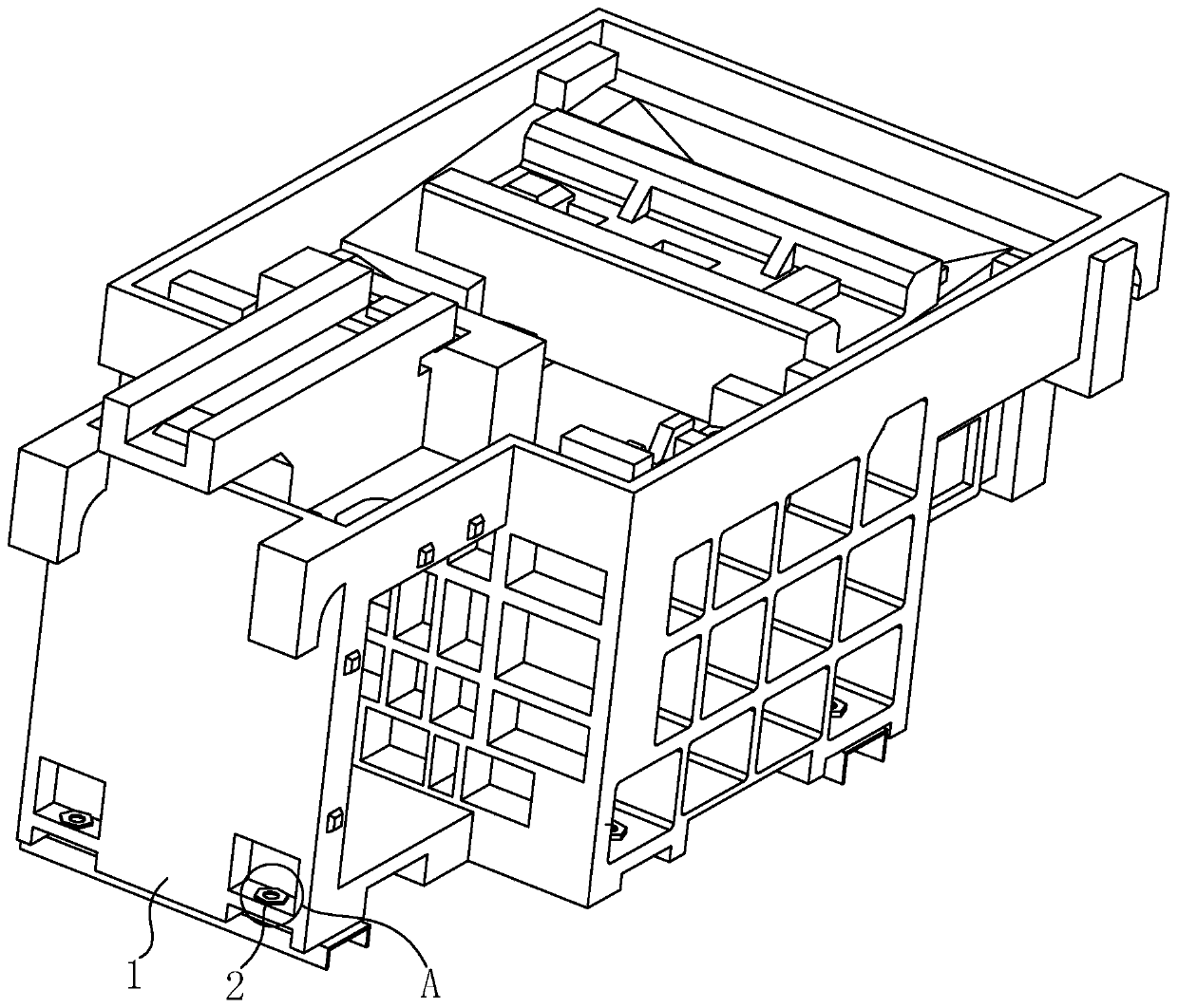
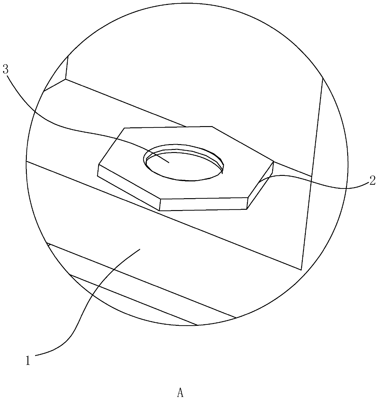
[0039] Embodiment one: machine tools, such as figure 1 and figure 2 As shown, a positioning nut 2 is formed on the machine tool body 1, and the side wall of the positioning nut 2 is completely covered by the machine tool body 1. At the same time, it can be as follows: Figure 6 In the structure of the positioning nut 2 shown in , an annular groove 9 is provided on the side wall of the positioning nut 2, so that when the positioning nut 2 is located in the machine tool body 1, the annular groove 9 is completely filled by the machine tool body 1 Complete, so that the protruding parts of the upper and lower ends of the positioning nut 2 are completely fitted and fixed by the machine tool body 1 to form an interference fit, so that even in the case of vibration, the positioning nut 2 will not be relative to the machine tool body. 1 shakes, thereby better ensuring the stability of the connection between the positioning nut 2 and the machine tool body 1, when the bolts and the pos...
Embodiment 2
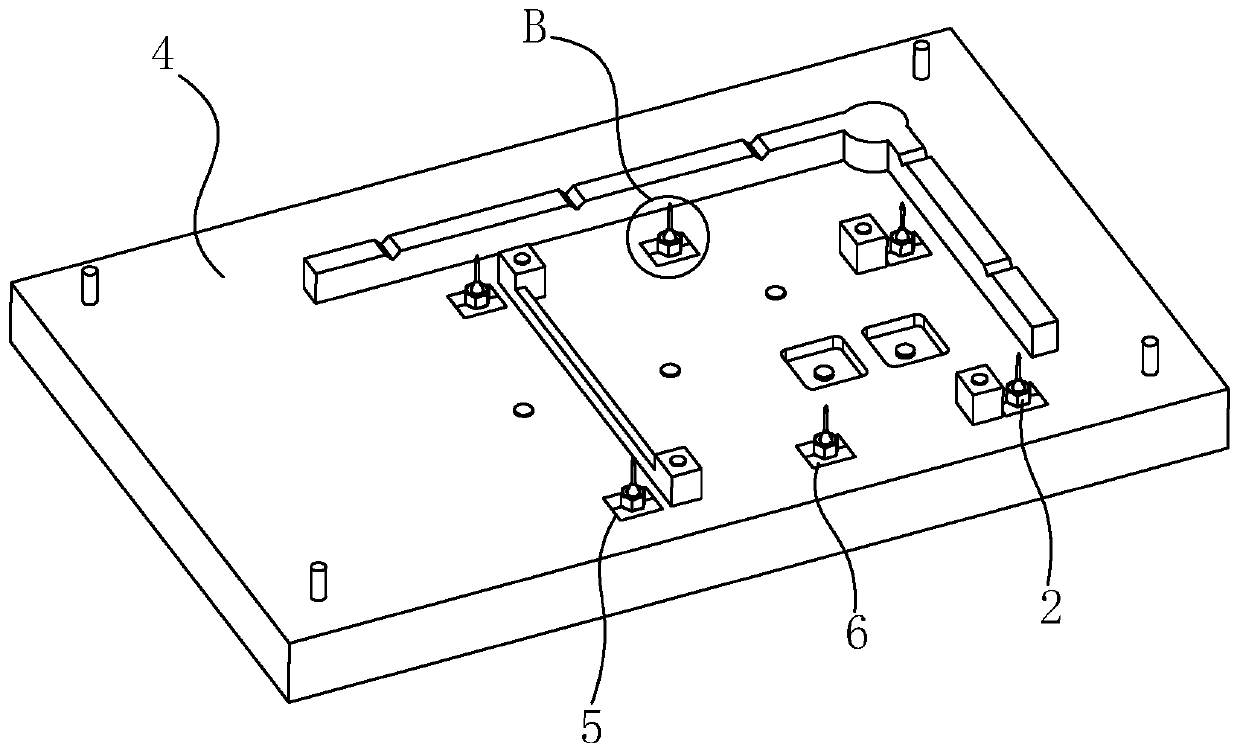
[0040] Embodiment two: in order to make the lathe in embodiment one conveniently, refer to Figure 3 to Figure 8 , a kind of processing method that is used to produce this lathe is provided now, the first step at first carries out making the machine tool mold that is used to make sand mold, the machine tool mold body 4 and the appearance of the machine tool body 1 that need to produce in the embodiment one keep basically the same At the same time, a reserved hole 5 is provided on the machine tool mold body 4, and the reserved hole 5 is used to place the positioning nut 2. Of course, for the convenience of fixing the positioning nut 2, at the same time, in order to make the positioning nut 2 can be aligned with the machine tool when forming The main body 1 is kept vertical, and two movable blocks 6 that cooperate with each other are arranged in the reserved hole 5, and a hole that is matched with each other is opened between the two movable blocks 6 for just being able to fit th...
Embodiment 3
[0045] Embodiment three: in order to cooperate with the technological needs of production machine tool, specially designed the machine tool mold that is used to make this machine tool, as Figure 3-Figure 7 The structure shown is a partial structural schematic diagram of the machine tool mold body 4, that is, a reserved hole 5 is opened on the machine tool mold body 4 at the position where the positioning nut 2 needs to be installed, and then two mutually spliced screws are installed in the reserved hole 5. The movable block 6, the positioning nut 2 is placed between the two movable blocks 6 to realize the clamping effect, and the reserved hole 5 is a structure with a large opening and a small bottom. 5 have the same structure, which is used to facilitate the installation of the movable block 6 and the movable block 6 is also easy to break away from during the demoulding process, so that the demoulding is fast and stable.
PUM
 Abstract
Description
Claims
Application Information
 - R&D
- Intellectual Property
- Life Sciences
- Materials
- Tech Scout
- Unparalleled Data Quality
- Higher Quality Content
- 60% Fewer Hallucinations
Browse by: Latest US Patents, China's latest patents, Technical Efficacy Thesaurus, Application Domain, Technology Topic, Popular Technical Reports.
© 2025 PatSnap. All rights reserved.Legal|Privacy policy|Modern Slavery Act Transparency Statement|Sitemap|About US| Contact US: help@patsnap.com