Die-casting mould

A die-casting mold and die-fixing technology, which is applied in the field of mechanical processing, can solve the problems of high cost and low molding rate, and achieve the effects of improving die-casting efficiency and yield, and reducing temperature

Inactive Publication Date: 2017-05-31
徐鹏威
View PDF0 Cites 8 Cited by
  • Summary
  • Abstract
  • Description
  • Claims
  • Application Information

AI Technical Summary

Problems solved by technology

In the past 20 years, the diversification of the die-casting industry has driven the transformation of China from a big die-casting country to a powerful die-casting country. Therefore, various die-casting molds have been developed, but there are many molds with low molding rates and high cost. Therefore, in order to To avoid the shortcomings of the above design, a new type of die-casting mold is designed here

Method used


Image

  • Die-casting mould
  • Die-casting mould
  • Die-casting mould

Examples


Embodiment 1

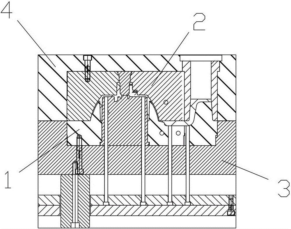
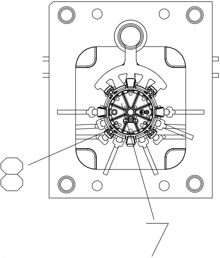
[0026] Such as figure 1 , figure 2 , image 3 , Figure 4 , Figure 5 , Image 6 , Figure 7 As shown, the die-casting mold provided by the present invention includes a movable mold 1, a fixed mold 2, a movable mold cover plate 3 and a fixed mold cover plate 4, and the movable mold cover plate 3 is set next to the movable mold 1, and the fixed mold cover plate 4 sets Then the fixed mold 2, the above-mentioned movable mold 1 and the fixed mold 2 cooperate with each other, and the first core insert 5 is arranged on the center position of the plane of the movable mold 1, and at the first core insert 5, set There is a first through hole 6 through the first core insert 5 and the movable mold 1, a second core insert 7 is arranged in the first through hole 6, and a second core insert 7 is arranged in the second core insert 7 One side is provided with a plurality of thimble holes 8, and a pair of bases 9 are connected to the bottom of the movable mold cover plate 3, and a thimb...

Embodiment 2

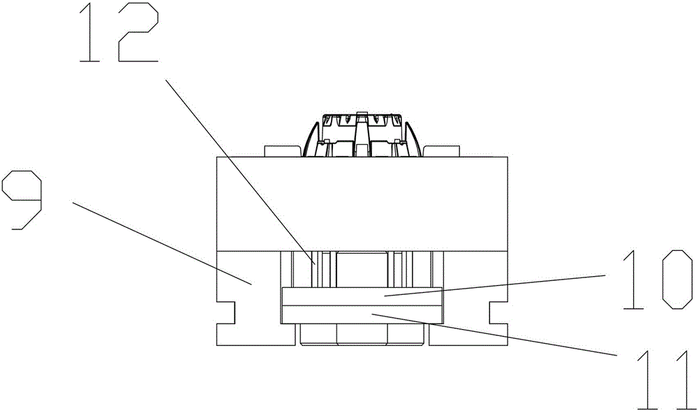
[0030] Such as Figure 8 , Figure 9 , Figure 10 , Figure 11 As shown, the general structure of the die-casting mold provided in this embodiment is consistent with that of Embodiment 1, the difference is that in order to protect the mould, the fixed mold 2 is provided with the fixed mold 2 and the fixed mold cover plate 4. Water pipe 23; in order to discharge impurities and waste gas, a plurality of overflow grooves 24 and exhaust grooves 25 are provided at the movable mold 1. In order to speed up the heat dissipation effect of the parts, the above-mentioned overflow grooves 25 are connected with heat dissipation plates 26 .


PUM


Abstract

The invention discloses a die-casting mould. The die-casting mould comprises a moving mould, a fixed mould, a moving mould sleeve plate and a fixed mould sleeve plate; a first mould core insert is arranged at the central position of a moving mould plane; the bottom of the moving mould sleeve plate is connected with a pair of bases in a matched manner; an ejector pin panel and an ejector pin base plate are arranged between the base plates; the ejector pin base plate is arranged below the ejector pin panel; the ejector pin base plate and the ejector pin panel are adhered to each other closely; guide posts are arranged at the four corners of the fixed mould sleeve plate; a second through hole which penetrates through the fixed mould sleeve plate is formed in the inside wall of the fixed mould sleeve plate; a sprue bush is arranged in the second through hole; guide sleeves which are matched with the guide posts are correspondingly arranged at the four corners of the moving mould sleeve plate; a transverse pouring channel and an inner pouring gate are formed in the moving mould. According to the die-casting mould, components can be in different shapes for production by replacing small mould cores in different shapes; the temperature can be reduced by arranging a water pipe at a mould cavity, and the die-casting efficiency and the yield can be improved.

Description

technical field [0001] The invention relates to the field of mechanical processing, in particular to a die-casting mold. Background technique [0002] Die casting is the abbreviation of pressure casting. It is a precision forming process in which metal parts are close to the final shape and size. The final product is die casting. Die casting is one of the most advanced metal forming methods, and it is an effective way to achieve less cutting and no cutting. Die-casting molding technology, plastic molding, and sheet metal stamping are listed as three major material molding systems. Die-casting industry is one of the basic processes of modern machinery manufacturing industry. With the development of the world's printing industry in the 1920s, it originated in the manufacture of movable type, and it has been less than 200 years. Compared with traditional casting technology, it is a young branch of casting technology, which has been applied to various industries and has become...

Claims


Application Information

Patent Timeline
Patent Type & Authority Applications(China)
IPC IPC(8): B22D17/22
CPCB22D17/229B22D17/2218
Inventor 徐鹏威
Owner 徐鹏威
Why Eureka
Try Eureka