Vehicle part cooling device

A technology for cooling devices and auto parts, applied in the furnace type, furnace, heat treatment furnace and other directions, can solve the problem of no support for accessories, and achieve the effect of avoiding uneven cooling

Active Publication Date: 2017-05-31
SHAOXING HUARUI AUTO PARTS CO LTD
View PDF8 Cites 2 Cited by
  • Summary
  • Abstract
  • Description
  • Claims
  • Application Information

AI Technical Summary

Problems solved by technology

[0003] The purpose of the present invention is to solve the shortcomings of the prior art that the air cooling is too time-consuming and the accessories have no support, and propose a cooling device for automobile parts

Method used


Image

  • Vehicle part cooling device
  • Vehicle part cooling device
  • Vehicle part cooling device

Examples


Embodiment Construction

[0015] The following will clearly and completely describe the technical solutions in the embodiments of the present invention with reference to the accompanying drawings in the embodiments of the present invention. Obviously, the described embodiments are only some, not all, embodiments of the present invention.

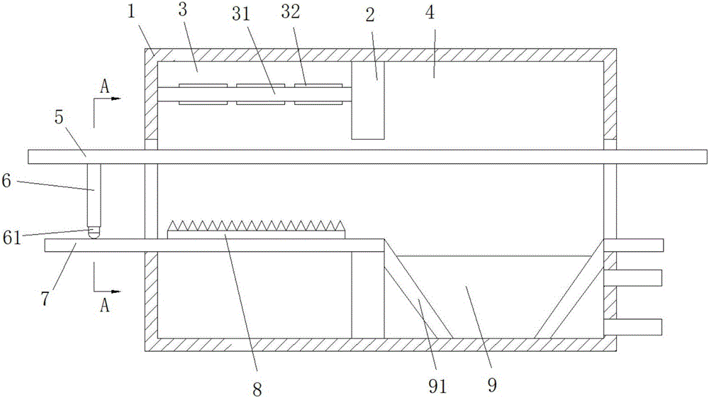
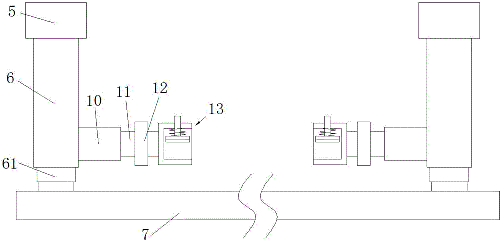
[0016] refer to Figure 1-3 , a cooling device for automobile parts, comprising a housing 1, two parallel conveying chains 5 disposed in the housing 1 and a carrier 7 located outside the housing below the conveying chain 5, a partition 2 is arranged in the housing 1, The clapboard 2 divides the inside of the shell 1 into an air-cooled chamber 3 and a water-cooled chamber 4. The top of the air-cooled chamber 3 is provided with a frame 31, and the frame 31 is provided with a rectangular arrangement of ventilation ducts 32, and a fan is installed in the ventilation duct 32.

[0017] A pool 9 is provided at the bottom of the water cooling chamber 4, and support plates 91...


PUM


Abstract

The invention relates to the technical field of vehicle manufacturing, in particular to a vehicle part cooling device. The vehicle part cooling device comprises a shell, two conveying chains inserted in the shell in parallel, and a carrier positioned below the conveying chains outside the shell; a separation plate is arranged in the shell for dividing the internal of the shell into an air cooling chamber and a water cooling chamber; the separation plate extends into the air cooling chamber; multiple sets of extension rods are arranged at the bottoms of the two conveying chains at equal intervals; two extension rods are in each set; pulleys are arranged at the bottoms of the extension rods, and are contacted with the carrier; sleeves are respectively mounted at the bottoms of the opposite inner sides of each set of extension rods; rotating shafts are mounted at one ends, far from the extension rods, of the sleeves through bearings; gears are sleeved on the rotating shafts; and clamping devices are mounted at the tail ends of the rotating shafts. The vehicle part cooling device is simple in structure and convenient to operate, and combines air cooling with water cooling to cool parts.

Description

technical field [0001] The invention relates to the technical field of automobile manufacturing, in particular to a cooling device for automobile parts. Background technique [0002] After the existing auto parts are casted by the casting machine and then taken out of the mold, the temperature is usually as high as 60°C, and they need to be cooled before they can go through the next process. If they are placed in the air to cool naturally, it takes 12 hours Left and right, a lot of time is wasted, and due to the high temperature and no support, the accessories may be deformed during the cooling process and cannot be used normally, and they cannot be directly put into water for rapid cooling, which will easily reduce the hardness of the accessories and cause internal cracks and other conditions. Contents of the invention [0003] The purpose of the present invention is to solve the shortcomings of the prior art that air cooling is too time-consuming and the accessories have...

Claims


Application Information

Patent Timeline
Patent Type & Authority Applications(China)
IPC IPC(8): B22D30/00C21D9/00
CPCB22D30/00C21D9/0062
Inventor 李志东罗小杰路越杰曲柯绮易钊诚
Owner SHAOXING HUARUI AUTO PARTS CO LTD
Why Eureka
Try Eureka